Introduction
This is a community effort to provide an open document about the Game Boy Advance (GBA).
The book is provided to you under the Creative Commons 0 License.
If you'd like to ask questions, report problems, or contribute, then go to our GitHub Repository.
If you want to just chat about GBA topics you can join the GBADev Discord.
The Basics
From the programmer's perspective, the system is composed of the following:
- CPU - A 16.78 Mhz ARM7tdmi
- Memory - 8 to 11 distinct areas of memory (depending on the Game Pak).
- IO - Special hardware functions available to the programmer, primarily pertaining to graphics, sound, DMA, timers, serial communication, key input, and interrupts.
Programs run on the GBA are usually contained in a "Game Pak". A "Game Pak" consists mainly of ROM and possibly Cart RAM (in the form of SRAM, Flash ROM, or EEPROM, used mainly for save game info). The ROM is where compiled code and data is stored. Unlike home computers, workstations, or servers, there are no disks or other drives, so everything that might otherwise have been stored as separate resource files must be compiled into the program ROM itself. Luckily there are tools to aid in this process.
The primary means a program accesses specialized hardware for graphics, sound, and other IO is through the memory-mapped IO. Memory mapped IO is a means of communicating with hardware by writing to/reading from specific memory addresses that are "mapped" to internal hardware functions. For example, you might write to address 0x04000000 with the value "0x0100", which tells the hardware "enable background 0 and graphics mode 0". A secondary means is through the BIOS, which is embedded in the internal GBA system ROM. Using software interrupts it is possible to access pre-programmed (and hopefully optimized) routines lying in the the system ROM. These routines then access the hardware through the memory-mapped IO.
Other regions of memory that are directly mapped to the hardware are Palette RAM (which is a table consisting of all the available colors), VRAM (which performs a similar function to the video RAM on a PC - and thensome), and OAM (which contains the attributes for hardware accelerated sprites).
Programming for the GBA
C, C++, and ARM/Thumb assembly are the most common languages used in GBA development, mainly because they are fast and relatively low level (i.e. there is a large degree of correspondance between the structure of the language and underlying instruction set of the architecture).
The two main development kits are devkitARM and gba-toolchain, but it's also surprisingly easy to roll your own using vanilla ARM GCC. Newer systems programming languages such as Rust, D, Nim and Zig are also increasingly used.
Most GBA programs are structured around the timing of the CPU and graphics hardware. The LCD has a refresh rate of about 59.73 hz, with each refresh consisting of a vertical draw period (when the GBA is drawing the screen) followed by a vertical blank period (when nothing is being drawn). The vertical draw and vertical blank periods are further subdivided into horizontal draw and blank periods. Programs typically use the VBlank and possibly the HBlank periods to update VRAM or graphics hardware registers in order to avoid unwanted visual artifacts, leaving the VDraw and HDraw periods to perform any software processing that will not effect the display. Common methods of syncing to VBlank include polling REG_DISPSTAT or REG_VCOUNT, calling the VBlankIntrWait BIOS function, or setting up an interrupt.
Memory
The following are the general areas of memory as seen by the CPU, and what they are used for.
System ROM
Start: 0x00000000
End:   0x00003FFF
Size:  16kb
Port Size: 32 bit
Wait State: 0
0x0 - 0x00003FFF contain the BIOS, which is executable but not readable. Any attempt to read in the area from 0x0 to 0x1FFFFFFF will result in failure; what you will see on a read is the current prefetched instruction (the instruction after the instruction used to view the memory area), thus giving the appearance that this area of memory consists of a repeating byte pattern.
External Work RAM
Start: 0x02000000
End:   0x0203FFFF
Size:  256kb
Port Size: 16 bit
Mirrors:  Every 0x40000 bytes from 0x02000000 to 0x02FFFFFF
This space is available for your game's data and code. If a multiboot cable is present on startup, the BIOS automatically detects it and downloads binary code from the cable and places it in this area, and execution begins with the instruction at address 0x02000000 (the default is 0x08000000). Though this is the largest area of RAM available on the GBA, memory transfers to and from EWRAM are 16 bits wide and thus consume more cycles than necessary for 32 bit accesses. Thus it is advised that 32 bit ARM code be placed in IWRAM rather than EWRAM.
Internal Work RAM
Start: 0x03000000
End:   0x03007FFF
Size:  32kb
Port Size: 32 bit
Mirrors:  Every 0x8000 bytes from 0x03000000 to 0x03FFFFFF
This space is also available for use. It is the fastest of all the GBA's RAM, being internally embedded in the ARM7 CPU chip package and having a 32 bit bus. As the bus for ROM and EWRAM is only 16 bits wide, the greatest efficiency will be gained by placing 32 bit ARM code in IWRAM while leaving thumb code for EWRAM or ROM memory.
IO Ram
Start: 0x04000000
End:   0x040003FF (0x04010000)
Size:  1Kb
Port Size:  Dual ported 32 bit
Mirrors:  The word at 0x04000800 (only!) is mirrored every 0x10000 bytes
          from 0x04000000 - 0x04FFFFFF.
This area contains a mirror of the ASIC (Application Specific Integrated Circuit) registers on the GBA. This area of memory is used to control the graphics, sound, DMA, and other features. See memory-mapped IO registers for details on the function of each register.
Palette RAM
Start: 0x05000000
End:   0x050003FF
Size:  1kb
Port Size:  16 bit
Mirrors: Every 0x400 bytes from 0x05000000 to 0x5FFFFFF
This area specifies the 16-bit color values for the paletted modes. There are two areas of the palette: one for backgrounds (0x05000000) and another for sprites (0x05000200). Each of these is either indexed as a single, 256-color palette, or as 16 individual 16-color palettes, depending on the settings of a particular sprite or background.
VRAM
Start: 0x06000000
End:   0x06017FFF
Size:  96kb
Port Size: 16 bit
Mirrors: Bytes 0x06010000 - 0x06017FFF is mirrored from 0x06018000 - 0x0601FFFF.
        The entire region from 0x06000000 - 0x06020000 is in turn mirrored every
        0x20000 bytes from 0x06000000 - 0x06FFFFFF.
The video RAM is used to store the frame buffer in bitmapped modes, and the tile data and tile maps for tile-based "text" and rotate/scale modes.
OAM
Start: 0x07000000
End:   0x070003FF
Size:  1kb
Port Size: 32 bit
Mirrors: Every 0x400 bytes from 0x07000000 to 0x07FFFFFF
This is the Object Attribute Memory, and is used to control the GBA's sprites.
The following areas of memory are technically cart-dependent, but can generally be expected to behave as described.
Game Pak ROM
Start: 0x08000000
Size:  The size of the cartridge (0 - 32 megabytes)
Port Size: 16 bit
Wait State: 0
The ROM in the game cartridge appears in this area. If a cartridge is present on startup, the instruction found at location 0x08000000 is loaded into the program counter and execution begins from there. Note that the transfers to and from ROM are all 16 bits wide.
Game Pak ROM Image 1
Start: 0x0A000000
Size:  The size of the cartridge (0 - 32 megabytes)
Port Size:  16 bit
Wait State: 1
This is a mirror of the ROM above. Used to allow multiple speed ROMs in a single game pak.
Game Pak ROM Image 2
Start: 0x0C000000
Size:  The size of the cartridge (0 - 32 megabytes)
Port Size: 16 bit
Wait State: 2
This is a mirror of the ROM above. Used to allow multiple speed ROMs in a single game pak.
Cart RAM
Start: 0x0E000000 (also seem to appear at 0x0F000000)
Size:  0 - 64 kb
Port Size: 8 bit
This is either SRAM or Flash ROM. Used primarily for saving game data. SRAM can be up to 64kb but is usually 32 kb. It has a battery backup so has the longest life (in terms of how many times it can be written to) of all backup methods. Flash ROM is usually 64 kb. Its lifespan is determined by the number of rewrites that can be done per sector (a 10,000 rewrite minimum is cited by some manufacturers).
EEPROM
This is another kind of cart memory, but operates differently from SRAM or Flash ROM. Unfortunately, I don't know the details of how it can be accessed by the programmer (send us a PR if you have more information on it). It uses a serial connection to transmit data. The maximum size is 128 mb, but it can be any size, and is usually 4 kb or 64 kb. Like Flash ROM it has a limited life; some manufacturers cite a minimum of 100,000 rewrites per sector.
There may be other regions of memory known as DEBUG ROM 1 and DEBUG ROM 2, though I really don't know whether these are a part of commercial carts or if they are mapped to some part of the internal ROM, or if they're even available on a standard GBA.
Note that EWRAM, IWRAM, VRAM, OAM, Palette RAM are all initialized to zero by the BIOS (i.e. you can expect them to be zeroed at startup).
Memory-Mapped Hardware Registers
The following section describes the function of each of the memory-mapped addresses in IO RAM. The register naming scheme is based on a variant of the popular gba.h by Eloist (specifically, that used by Uze in the examples on his Audio Advance site).
The notation for each entry is as follows:
                           R       <- 'R' means "Read Only", 'W' means "Write Only"
F E D C  B A 9 8  7 6 5 4  3 2 1 0   <- These are the bits
W V U S  L K J I  F D B A  C M M M   <- These letters are used in the key.
                                     Entries marked with an 'X' usually
                                     serve no function, are unwriteable,
                                     and remain at 0.
Hardware Register Summary
| Starting Address | Region name |
|---|---|
| 0x04000000 | Display |
| 0x04000060 | Sound |
| - Alternative DMG Sound register names | |
| 0x040000B0 | DMA |
| 0x04000100 | Timers |
| 0x04000120 | Serial hardware control and data |
| - Normal / SPI mode | |
| - Multiplay mode | |
| - UART mode | |
| 0x04000130 | Keypad button input and interrupt control |
| 0x04000134 | Serial port mode and control |
| 0x04000140 | JOYBUS controller |
| 0x04000200 | Interrupt controller |
| - Cartridge slot waitstate and control | |
| 0x04000300 | System control |
Display
| Address | Name | Size | Description |
|---|---|---|---|
| 0x04000000 | DISPCNT | 16 | Display Control |
| 0x04000002 | 16 | Stereoscopic mode enable | |
| 0x04000004 | DISPSTAT | 16 | Display Status, display interrupt enable, Line Y Compare (LYC) |
| 0x04000006 | VCOUNT | 16 | Current display scanline position (equivalent to LY on 8-bit Game Boy systems) |
| 0x04000008 | BG0CNT | 16 | Background Control |
| 0x0400000A | BG1CNT | ^^ | ^^ |
| 0x0400000C | BG2CNT | ^^ | ^^ |
| 0x0400000E | BG3CNT | ^^ | ^^ |
| 0x04000010 | BG0HOFS | 16 | Background Scrolling |
| 0x04000012 | BG0VOFS | ^^ | ^^ |
| 0x04000014 | BG1HOFS | ^^ | ^^ |
| 0x04000016 | BG1VOFS | ^^ | ^^ |
| 0x04000018 | BG2HOFS | ^^ | ^^ |
| 0x0400001A | BG2VOFS | ^^ | ^^ |
| 0x0400001C | BG3HOFS | ^^ | ^^ |
| 0x0400001E | BG3VOFS | ^^ | ^^ |
| 0x04000020 | BG2PA | 16 | Background Affine parameters for BG2 |
| 0x04000022 | BG2PB | 16 | ^^ |
| 0x04000024 | BG2PC | 16 | ^^ |
| 0x04000026 | BG2PD | 16 | ^^ |
| 0x04000028 | BG2X | 32 | ^^ |
| 0x0400002C | BG2Y | 32 | ^^ |
| 0x04000030 | BG3PA | 16 | Background Affine parameters for BG3 |
| 0x04000032 | BG3PB | 16 | ^^ |
| 0x04000034 | BG3PC | 16 | ^^ |
| 0x04000036 | BG3PD | 16 | ^^ |
| 0x04000038 | BG3X | 32 | ^^ |
| 0x0400003C | BG3Y | 32 | ^^ |
| 0x04000040 | WIN0H | 16 | Window Bounds |
| 0x04000042 | WIN1H | 16 | ^^ |
| 0x04000044 | WIN0V | 16 | ^^ |
| 0x04000046 | WIN1V | 16 | ^^ |
| 0x04000048 | WININ | 16 | Window display inside of WIN0 and WIN1 |
| 0x0400004A | WINOUT | 16 | Window display outside of WIN0 and WIN1, and inside of OBJWIN |
| 0x0400004C | MOSAIC | 16 | Mosaic effect size |
| 0x04000050 | BLDCNT | 16 | Blend mode and target selection |
| 0x04000052 | BLDALPHA | 16 | Blend alpha coefficients |
| 0x04000054 | BLDY | 16 | Blend luminance coefficient for lightening and darkening |
Sound
| Address | Name | Size | Description |
|---|---|---|---|
| 0x04000060 | SOUND1CNT_L | 16 | DMG Sound Channel 1 |
| 0x04000062 | SOUND1CNT_H | 16 | ^^ |
| 0x04000064 | SOUND1CNT_X | 16 | ^^ |
| 0x04000068 | SOUND2CNT_L | 16 | DMG Sound Channel 2 |
| 0x0400006C | SOUND2CNT_H | 16 | ^^ |
| 0x04000070 | SOUND3CNT_L | 16 | DMG Sound Channel 3 |
| 0x04000072 | SOUND3CNT_H | 16 | ^^ |
| 0x04000074 | SOUND3CNT_X | 16 | ^^ |
| 0x04000078 | SOUND4CNT_L | 16 | DMG Sound Channel 4 |
| 0x0400007C | SOUND4CNT_H | 16 | ^^ |
| 0x04000080 | SOUNDCNT_L | 16 | DMG Sound master volume and pan |
| 0x04000082 | SOUNDCNT_H | 16 | GBA Sound volume mixing and Direct Sound control |
| 0x04000084 | SOUNDCNT_X | 16 | Sound master enable and DMG Sound channel status |
| 0x04000088 | SOUNDBIAS | 16 | PWM bias and resolution |
| 0x040000A0 | FIFO_A | 32(!) | Direct Sound FIFO A |
| 0x040000A4 | FIFO_B | 32(!) | Direct Sound FIFO B |
Alternative DMG Sound register names
| Address | Name | Description |
|---|---|---|
| 0x04000060 | NR10 | DMG Sound Channel 1 |
| 0x04000062 | NR11 | ^^ |
| 0x04000063 | NR12 | ^^ |
| 0x04000064 | NR13 | ^^ |
| 0x04000065 | NR14 | ^^ |
| 0x04000068 | NR21 | DMG Sound Channel 2 |
| 0x04000069 | NR22 | ^^ |
| 0x0400006C | NR23 | ^^ |
| 0x0400006D | NR24 | ^^ |
| 0x04000070 | NR30 | DMG Sound Channel 3 |
| 0x04000072 | NR31 | ^^ |
| 0x04000073 | NR32 | ^^ |
| 0x04000074 | NR33 | ^^ |
| 0x04000075 | NR34 | ^^ |
| 0x04000078 | NR41 | DMG Sound Channel 4 |
| 0x04000079 | NR42 | ^^ |
| 0x0400007C | NR43 | ^^ |
| 0x0400007D | NR44 | ^^ |
| 0x04000080 | NR50 | DMG Sound master volume |
| 0x04000081 | NR51 | DMG Sound channel pan |
| 0x04000084 | NR52 | Sound master enable and channel status |
DMA
| Address | Name | Size | Description |
|---|---|---|---|
| 0x040000B0 | DMA0SAD | 32 | DMA Controller 0 |
| 0x040000B4 | DMA0DAD | 32 | ^^ |
| 0x040000B8 | DMA0CNT_L | 16 | ^^ |
| 0x040000BA | DMA0CNT_H | 16 | ^^ |
| 0x040000BC | DMA1SAD | 32 | DMA Controller 1 |
| 0x040000C0 | DMA1DAD | 32 | ^^ |
| 0x040000C4 | DMA1CNT_L | 16 | ^^ |
| 0x040000C6 | DMA1CNT_H | 16 | ^^ |
| 0x040000C8 | DMA2SAD | 32 | DMA Controller 2 |
| 0x040000CC | DMA2DAD | 32 | ^^ |
| 0x040000D0 | DMA2CNT_L | 16 | ^^ |
| 0x040000D2 | DMA2CNT_H | 16 | ^^ |
| 0x040000D4 | DMA3SAD | 32 | DMA Controller 3 |
| 0x040000D8 | DMA3DAD | 32 | ^^ |
| 0x040000DC | DMA3CNT_L | 16 | ^^ |
| 0x040000DE | DMA3CNT_H | 16 | ^^ |
Timer
| Address | Name | Size | Description |
|---|---|---|---|
| 0x04000100 | TM0D | 16 | Timer 0 |
| 0x04000102 | TM0CNT | 16 | ^^ |
| 0x04000104 | TM1D | 16 | Timer 1 |
| 0x04000106 | TM1CNT | 16 | ^^ |
| 0x04000108 | TM2D | 16 | Timer 2 |
| 0x0400010A | TM2CNT | 16 | ^^ |
| 0x0400010C | TM3D | 16 | Timer 3 |
| 0x0400010E | TM3CNT | 16 | ^^ |
Serial peripherals
See Serial port mode and control to switch to the correct mode.
Normal / SPI
| Address | Name | Size | Description |
|---|---|---|---|
| 0x04000128 | SCCNT_L | 16 | Serial peripheral mode, status, and control |
| 0x0400012A | SCCNT_H | 8 | Serial data send and receive |
Multiplay
| Address | Name | Size | Description |
|---|---|---|---|
| 0x04000120 | SCD0 | 16 | Multiplay received data from master |
| 0x04000122 | SCD1 | 16 | Multiplay received data from slave 1 |
| 0x04000124 | SCD2 | 16 | Multiplay received data from slave 2 |
| 0x04000126 | SCD3 | 16 | Multiplay received data from slave 3 |
| 0x04000128 | SCCNT_L | 16 | Serial peripheral mode, status, and control |
| 0x0400012A | SCCNT_H | 16 | Multiplay transmit value |
UART
| Address | Name | Size | Description |
|---|---|---|---|
| 0x04000128 | SCCNT_L | 16 | Serial peripheral mode, status, and control |
| 0x0400012A | SCCNT_H | 8 | UART send (W) and receive (R) FIFO |
Keypad
| Address | Name | Size | Description |
|---|---|---|---|
| 0x04000130 | KEYINPUT | 16 | Keypad input |
| 0x04000132 | KEYCNT | 16 | Keypad wake and interrupt control |
Serial port (EXT.) control
| Address | Name | Size | Description |
|---|---|---|---|
| 0x04000134 | RCNT | 16 | Port mode control, GPIO direction and value, GPIO interrupt enable |
JOYBUS
TODO: JOYBUS is not explored enough yet to be documented here.
Interrupts
| Address | Name | Size | Description |
|---|---|---|---|
| 0x04000200 | IE | 16 | Interrupt enable selection |
| 0x04000202 | IF | 16 | Interrupt status and acknowledge |
| 0x04000208 | IME | 32 | Interrupt Master Enable |
Cartridge slot control
| Address | Name | Size | Description |
|---|---|---|---|
| 0x04000204 | WAITCNT | 16 | Cartridge waitstate control, clock output, prefetch enable, and cartridge shape status |
System control
| Address | Name | Size | Description |
|---|---|---|---|
| 0x04000300 | HALTCNT | 16 | Low-power mode control and boot flag status |
| 0x04000800 | 32 | (Only on AGB, AGS, GBP, and OXY) Test mode control |
0x04000000 - 0x04000054 - Graphics Hardware Registers
0x04000000 - REG_DISPCNT (The display control register)
                           R
F E D C  B A 9 8  7 6 5 4  3 2 1 0
W V U S  L K J I  F D B A  C M M M
| Bits | Description |
|---|---|
| 0-2 (M) | The video mode. See video modes for details. |
| 3 (C) | Game Boy Color mode. Read only - should stay at 0. |
| 4 (A) | This bit controls the starting address of the bitmap in bitmapped modes and is used for page flipping. See the description of the specific video mode for details. |
| 5 (B) | Force processing during hblank. Setting this causes the display controller to process data earlier and longer, beginning from the end of the previous scanline up to the end of the current one. This added processing time can help prevent flickering when there are too many sprites on a scanline. |
| 6 (D) | Sets whether sprites stored in VRAM use 1 dimension or 2. 0 = 2D: each row of tiles is stored 32x64 bytes in from the start of the previous row. 1 = 1D: tiles are are stored sequentially. |
| 7 (F) | Force the display to go blank when set. This can be used to save power when the display isn't needed, or to blank the screen when it is being built up (such as in mode 3, which has only one framebuffer). On the SNES, transfers rates to VRAM were improved during a forced blank; it is logical to assume that this would also hold true on the GBA. |
| 8 (I) | If set, enable display of BG0. |
| 9 (J) | If set, enable display of BG1. |
| A (K) | If set, enable display of BG2. |
| B (L) | If set, enable display of BG3. |
| C (S) | If set, enable display of sprites. |
| D (U) | Enable Window 0 |
| E (V) | Enable Window 1 |
| F (W) | Enable Sprite Windows |
0x04000004 - REG_DISPSTAT
                             R R R
F E D C  B A 9 8  7 6 5 4  3 2 1 0
T T T T  T T T T  X X Y H  V Z G W
| Bits | Description |
|---|---|
| 0 (W) | V Refresh status. This will be 0 during VDraw, and 1 during VBlank. VDraw lasts for 160 scanlines; VBlank follows after that and lasts 68 scanlines. Checking this is one alternative to checking REG_VCOUNT. |
| 1 (G) | H Refresh status. This will be 0 during HDraw, and 1 during HBlank HDraw lasts for approximately 1004 cycles; HBlank follows, and lasts approximately 228 cycles, though the time and length of HBlank may in fact vary based on the number of sprites and on rotation/scaling/blending effects being performed on the current line. |
| 2 (Z) | VCount Triggered Status. Gets set to 1 when a Y trigger interrupt occurs. |
| 3 (V) | Enables LCD's VBlank IRQ. This interrupt goes off at the start of VBlank. |
| 4 (H) | Enables LCD's HBlank IRQ. This interrupt goes off at the start of HBlank. |
| 5 (Y) | Enable VCount trigger IRQ. Goes off when VCount line trigger is reached. |
| 8-F (T) | Vcount line trigger. Set this to the VCount value you wish to trigger an interrupt. |
0x04000006 - LCY / REG_VCOUNT (Read Only)
This location stores the current y location of the LCD hardware. It is incremented as the lines are drawn. The 160 lines of display are followed by 68 lines of Vblank period, before the whole thing starts again for the next frame. Waiting for this register to reach 160 is one way to synchronize a program to 60Hz.
0x04000008 - 0x0400001E - Background Registers
0x04000008 - REG_BG0CNT
0x0400000A - REG_BG1CNT
0x0400000C - REG_BG2CNT
0x0400000E - REG_BG3CNT
These addresses set up the four background layers. The format is:
    ?
F E D C  B A 9 8  7 6 5 4  3 2 1 0
Z Z V M  M M M M  A C X X  S S P P
| Bits | Description |
|---|---|
| 0-1 (P) | Priority: Priorities are ordered as follows: "Front" When multiple backgrounds have the same priority, the order from front to back is: BG0, BG1, BG2, BG3. Sprites of the same priority are ordered similarly, with the first sprite in OAM appearing in front. |
| 2-3 (S) | Starting address of character tile data Address = 0x06000000 + S * 0x4000 |
| 6 (C) | Mosiac effect - 1 on, 0 off |
| 7 (A) | Color palette type - 1 - standard 256 color pallete 0 - each tile uses one of 16 different 16 color palettes (no effect on rotates/scale backgrounds, which are always 256 color) |
| 8-C (M) | Starting address of character tile map Address = 0x06000000 + M * 0x800 |
| D (V) | Screen Over. Used to determine whether rotational backgrounds get tiled repeatedly at the edges or are displayed as a single "tile" with the area outside transparent. This is forced to 0 (read only) for backgrounds 0 and 1 (only). |
| E-F (Z) | Size of tile map For "text" backgrounds:
|
0x04000010 - REG_BG0HOFS Horizontal scroll co-ordinate for BG0 (Write Only)
0x04000012 - REG_BG0VOFS Vertical scroll co-ordinate for BG0 (Write Only)
0x04000014 - REG_BG1HOFS Horizontal scroll co-ordinate for BG1 (Write Only)
0x04000016 - REG_BG1VOFS Vertical scroll co-ordinate for BG1 (Write Only)
0x04000018 - REG_BG2HOFS Horizontal scroll co-ordinate for BG2 (Write Only)
0x0400001A - REG_BG2VOFS Vertical scroll co-ordinate for BG2 (Write Only)
0x0400001C - REG_BG3HOFS Horizontal scroll co-ordinate for BG3 (Write Only)
0x0400001E - REG_BG3VOFS Vertical scroll co-ordinate for BG3 (Write Only)
F E D C  B A 9 8  7 6 5 4  3 2 1 0
X X X X  X X S S  S S S S  S S S S
0-9 (S) = Scroll value (pixels)
These registers are only effective for text backgrounds; they set the pixel that is displayed in the top left hand corner of the GBA's display. In other words, a value of -5, -5 puts the upper left hand corner of your background at x=5,y=5. All four BG planes wrap when they reach their right or bottom edges.
0x04000020 - 0x04000026 / 0x04000030 - 0x04000036 - Background Rotation/Scaling Registers (Write Only)
These registers affect the translation, rotation, and scaling of tile-based rotate/scale backgrounds as well as the bitmapped backgrounds (which should be treated as BG2 for this purpose). The function of these registers is very hard to describe in words but easy to see the effects of on screen. I highly recommend checking out Stephen Stair's RSDemo - it lets you see the contents of the regs as you modify them as well as the effect they have on the background. Should also be somewhat useful for figuring out sprite rotation and scaling.
F E D C  B A 9 8  7 6 5 4  3 2 1 0
S I I I  I I I I  F F F F  F F F F
| Bits | Description |
|---|---|
| 0-7 (F) | Fraction |
| 8-E (I) | Integer |
| F (S) | Sign bit |
These registers apply only to Rotate/Scale backgrounds. Individual descriptions follow:
0x04000020 - REG_BG2PA (BG2 Read Source Pixel X Increment) (Write Only)
0x04000030 - REG_BG3PA (BG3 Read Source Pixel X Increment) (Write Only)
The effect of these registers is to scale the background (relative to the upper left corner) in the x direction by an amount equal to 1/(register value).
0x04000022 - REG_BG2PB (BG2 Write Destination Pixel X Increment) (Write Only)
0x04000032 - REG_BG3PB (BG3 Write Destination Pixel X Increment) (Write Only)
The effect of these registers is to shear the x coordinates of the background over y, relative to the upper left corner. A value of 0 will result in no shearing, a value of 1.00 will make the background appear to be sheared left as you go down the screen, and a value of -1 will make the background appear sheared right as you go down the screen.
0x04000024 - REG_BG2PC (BG2 Read Source Pixel Y Increment) (Write Only)
0x04000034 - REG_BG3PC (BG3 Read Source Pixel Y Increment) (Write Only)
The effect of these registers is to shear the y coordinates of the background over x, relative to the upper left corner. A value of 0 will result in no shearing, a value of 1.00 will make the background appear to be sheared upwards to the right, and a value of -1 will make the background appear sheared downwards and to the right.
0x04000026 - REG_BG2PD (BG2 Write Destination Pixel Y Increment) (Write Only)
0x04000036 - REG_BG3PD (BG3 Write Destination Pixel Y Increment) (Write Only)
The effect of these registers is to scale the background in the y direction (relative to the upper left corner) by an amount equal to 1/(register value).
0x04000028 - REG_BG2X (X Coordinate for BG2 Rotational Background) (Write Only)
0x04000038 - REG_BG3X (X Coordinate for BG3 Rotational Background) (Write Only)
0x0400002C - REG_BG2Y (Y Coordinate for BG2 Rotational Background) (Write Only)
0x0400003C - REG_BG3Y (Y Coordinate for BG3 Rotational Background) (Write Only)
31 30 29 28  27 26 25 24  23 22 21 20  19 18 17 16  15 14 13 12  11 10 9 8  7 6 5 4  3 2 1 0
X  X  X  X   S  I  I  I   I  I  I  I   I  I  I  I   I  I  I  I   I  I  I I  F F F F  F F F F
| Bits | Description |
|---|---|
| 0-7(F) | Fraction |
| 8-26(I) | Integer |
| 27(S) | Sign bit |
These registers define the location of the pixel that appears at 0,0. They are very similar to the background scrolling registers, REG_HOFS and REG_VOFS, which become disabled when a rotate/ scale background is in use.
0x04000040 - 0x0400004A - Windowing Registers
0x04000040 - REG_WIN0H Window 0 X Coordinates) (Write Only)
0x04000042 - REG_WIN1H Window 1 X Coordinates) (Write Only)
F E D C  B A 9 8  7 6 5 4  3 2 1 0
L L L L  L L L L  R R R R  R R R R
| Bits | Description |
|---|---|
| 0-7 (R) | X coordinate for the rightmost side of the window |
| 8-F (L) | X coordinate for the leftmost side of the window |
0x04000044 - REG_WIN0V Window 0 Y Coordinates) (Write Only)
0x04000046 - REG_WIN1V Window 1 Y Coordinates) (Write Only)
F E D C  B A 9 8  7 6 5 4  3 2 1 0
T T T T  T T T T  B B B B  B B B B
| Bits | Description |
|---|---|
| 0-7 (B) | Y coordinate for the bottom of the window |
| 8-F (T) | Y coordinate for the top of the window |
0x04000048 - REG_WININ (Inside Window Settings)
F E D C  B A 9 8  7 6 5 4  3 2 1 0
X X T S  R Q P O  X X L K  J I H G
| Bits | Description |
|---|---|
| 0 (G) | BG0 in win0 |
| 1 (H) | BG1 in win0 |
| 2 (I) | BG2 in win0 |
| 3 (J) | BG3 in win0 |
| 4 (K) | Sprites in win0 |
| 5 (L) | Blends in win0 |
| 8 (O) | BG0 in win1 |
| 9 (P) | BG1 in win1 |
| A (Q) | BG2 in win1 |
| B (R) | BG3 in win1 |
| C (S) | Sprites in win1 |
| D (T) | Blends in win1 |
0x0400004A - REG_WINOUT (Outside Window and Sprite Window)
F E D C  B A 9 8  7 6 5 4  3 2 1 0
X X T S  R Q P O  X X L K  J I H G
| Bits | Description |
|---|---|
| 0 (G) | BG0 outside |
| 1 (H) | BG1 outside |
| 2 (I) | BG2 outside |
| 3 (J) | BG3 outside |
| 4 (K) | Sprites in win0 |
| 5 (L) | Blends in win0 |
| 8 (O) | BG0 in sprite win |
| 9 (P) | BG1 in sprite win |
| A (Q) | BG2 in sprite win |
| B (R) | BG3 in sprite win |
| C (S) | Sprites in sprite win |
| D (T) | Blends in sprite win |
0x0400004C - 0x04000054 - Effects Registers
0x0400004C - REG_MOSAIC (Write Only)
F E D C  B A 9 8  7 6 5 4  3 2 1 0
V V V V  U U U U  J J J J  I I I I
| Bits | Description |
|---|---|
| 0-3 (I) | BG X Size |
| 4-7 (J) | BG Y Size |
| 8-B (U) | Sprite X Size |
| C-F (V) | Sprite Y Size |
Use this register to control the size of the mosaic on backgrounds/sprites that have mosaic enabled..
0x04000050 - REG_BLDCNT
F E D C  B A 9 8  7 6 5 4  3 2 1 0
X X T S  R Q P O  M M L K  J I H G
| Bits | Description |
|---|---|
| 0 (G) | Blend BG0 (source) |
| 1 (H) | Blend Bg1 (source) |
| 2 (I) | Blend BG2 (source) |
| 3 (J) | Blend BG3 (source) |
| 4 (K) | Blend sprites (source) |
| 5 (L) | Blend backdrop (source) |
| 6-7 (M) | Blend Mode There are four different modes:
|
| 8 (O) | Blend BG0 (target) |
| 9 (P) | Blend BG1 (target) |
| A (Q) | Blend BG2 (target) |
| B (R) | Blend BG3 (target) |
| C (S) | Blend sprites (target) |
| D (T) | Blend backdrop (target) |
Use this register to determine the blending mode and which layer(s) you wish to perform blending on. In the case of alpha blends (Mode 01), specify the layers that are "on top" using the source flags (bits 0 - 5) and the layers that are on the bottom using the target flags (bits 8-13). The target layer must be below the source layer in terms of its priority, or the blend will not take effect.
Other things to note about alpha blends:
- If there is more than one target layer, the blend will only occur for a target with lower priority in areas where it shows through targets of higher priority due to the transparent pixel being set
- Source layers will only blend with areas of a target layer that are visible beneath them. If another layer is blocking the way (even if it is another source layer), there will be no blend and the original source color will be drawn.
- As a result of these two conditions, it is never possible for any given pixel to be a blend of more than 2 layers. This eliminates the possiblity of using these registers to have 3 or more layers of translucent graphics showing through one another.
- A layer cannot blend with itself.
- If an obj has semi-transparency enabled, it will blend normally (as if it were specified as a source layer)
- Unfortunately, it is not possible to alpha blend sprites against one another, no matter how your prioritize them. Alpha blended sprites that are "in front of" other sprites will blend with the other target layers while still occluding the sprites behind them (i.e. it will look like the portion of the non-blended sprite that is behind the blended one has disappeared), for a most unnatural effect.
0x04000052 - REG_BLDALPHA (Write Only)
F E D C  B A 9 8  7 6 5 4  3 2 1 0
X X X B  B B B B  X X X A  A A A A
| Bits | Description |
|---|---|
| 0-4 (A) | Coefficient A, the source pixel (layer above) |
| 8-C (B) | Coefficient B, the target pixel (layer below) |
Use this in conjunction with REG_BLDCNT to determine the amount of blending between layers. An unblended pixel of normal intensity is is considered to have a coefficient of 16. Coefficient A and Coefficient B determine the ratio of each of the sources that will get mixed into the final image. Thus, if A is 12 and B is 4, the resulting image will appear to be 12/16 the color of A and 4/16 the color of B. Note that A and B can add up to be greater than 16 (for an additive or brightening effect) or less than 16 (for a darkening effect).
0x04000054 - REG_BLDY (Write Only)
F E D C  B A 9 8  7 6 5 4  3 2 1 0
X X X X  X X X X  X X X F  F F F F
| Bits | Description |
|---|---|
| 0-4 (F) | The lighten/darken value |
This is the amount by which to lighten or darken the source layers (as specified in REG_BLDCNT) . The higher the value, the greater the fade. 16 is the peak fade value; values from 16 - 31 shade the layer with either pure black (for a darken) or pure white (for a lighten).
0x040000060 - 0x0400000A6 (Sound Controls)
Note: I've obtained this info (most of it verbatim) from Uze's BeLogic unofficial GBA sound info site, which gives a much more thorough explanation as well as some sample source code and demos. Thanks to Uze for providing such a great resource on GBA sound.
0x04000060 - REG_SOUND1CNT_L (Sound 1 Sweep control)
F E D C  B A 9 8  7 6 5 4  3 2 1 0
X X X X  X X X X  X T T T  A S S S
| Bits | Description |
|---|---|
| 0-2 (S) | Number of sweep shifts. These control the amount of change in frequency (either increase or decrease) at each change. The wave's new period is given by: T=T±T/(2n), where n is the sweep shift's value. |
| 3 (A) | Sweep increase or decrease. When decrementing, if the frequency value gets smaller than zero, the previous value is retained. When incrementing, if the frequency gets greater than the maximum frequency (131Khz or 2048 for the register value) the sound stops.
|
| 4-6 (T) | Sweep Time. This is the delay between sweep shifts. After each delay, the frequency increments or decrements.
|
Sound channel 1 produces a square wave with envelope and frequency sweep functions. This register controls the frequency sweep function. When the sweep function is not required, set the sweep time to zero and set the increase/decrease bit to 1.
0x04000062 - REG_SOUND1CNT_H (Sound 1 Length, wave duty and envelope control)
                      W W  W W W W
F E D C  B A 9 8  7 6 5 4  3 2 1 0
I I I I  M T T T  D D L L  L L L L
| Bits | Description |
|---|---|
| 0-5 (L) | Sound length. This is a 6 bit value obtained from the following formula:
After the sound length has been changed, the sound channel must be resetted via bit |
| 6-7 (D) | Wave duty cycle. This controls the percentage of the ON state of the square wave.
|
| 8-A (T) | Envelope step time. This is the delay between successive envelope increase or decrease. It is given by the following formula:
|
| B (M) | Envelope mode. Controls if the envelope is to increase or decrease in volume over time.
|
| C-F (I) | Initial Envelope value. |
0x04000064 - REG_SOUND1CNT_X (Sound 1 Frequency, reset and loop control)
W          W W W  W W W W  W W W W
F E D C  B A 9 8  7 6 5 4  3 2 1 0
R T X X  X F F F  F F F F  F F F F
| Bits | Description |
|---|---|
| 0-A (F) | Sound frequency. The minimum frequency is 64Hz and the maximum is 131Khz. Can be calculated from the following formula:
|
| E (T) | Timed sound. When set to 0, sound 1 is played continuously regardless of the length data in REG_SOUND1CNT_H. When set to 1, sound is played for that specified length and after that, bit 0 of REG_SOUNDCNT_X is reset. |
| F (R) | Sound reset. When set, sound resets and restarts at the specified frequency. When sound 1 is playing, modifying the volume envelope bits has no effect until the sound is resetted. Frequency and sound reset must be perfomed in a single write since both are write only. Frequency can always be changed without resetting the sound channel. |
0x04000068 - REG_SOUND2CNT_L (Sound 2 Length, wave duty and envelope control)
                      W W  W W W W
F E D C  B A 9 8  7 6 5 4  3 2 1 0
I I I I  M T T T  D D L L  L L L L
| Bits | Description |
|---|---|
| 0-5 (L) | Sound length. This is a 6 bit value obtained from the following formula:
After the sound length has been changed, the sound channel must be resetted via bit F of REG_SOUND1CNT_X (when using timed mode). |
| 6-7 (D) | Wave duty cycle. This controls the percentage of the ON state of the square wave.
|
| 8-A (T) | Envelope step time. This is the delay between successive envelope increase or decrease. It is given by the following formula:
|
| B (M) | Envelope mode. Controls if the envelope is to increase or decrease in volume over time.
|
| C-F (I) | Initial Envelope value. |
0x0400006C- REG_SOUND2CNT_H (Sound 2 Frequency, reset and loop control)
W          W W W  W W W W  W W W W
F E D C  B A 9 8  7 6 5 4  3 2 1 0
R T X X  X F F F  F F F F  F F F F
| Bits | Description |
|---|---|
| 0-A (F) | Sound frequency. The minimum frequency is 64Hz and the maximum is 131Khz. Can be calculated from the following formula:
|
| E (T) | Timed sound. When set to 0, sound 2 is played continuously regardless of the length data in REG_SOUND2CNT_L. When set to 1, sound is played for that specified length and after that, bit 1 of REG_SOUNDCNT_X is reset. |
| F (R) | Sound reset. When set, sound resets and restarts at the specified frequency. When sound 2 is playing, modifying the volume envelope bits has no effect until the sound is resetted. Frequency and sound reset must be perfomed in a single write since both are write only. Frequency can always be changed without resetting the sound channel. |
0x04000070 - REG_SOUND3CNT_L (Sound 3 Enable and wave ram bank control)
F E D C  B A 9 8  7 6 5 4  3 2 1 0
X X X X  X X X X  N S M X  X X X X
| Bits | Description |
|---|---|
| 5 (M) | Bank Mode (0 = 2 x 32 sample banks, 1 = 1 x 64 sample bank) |
| 6 (S) | Bank Select. Controls which bank is active for playing/reloading. If set to 0, samples are played from bank 0 and writing to the Wave Ram will store the data in Bank 1, and vice-versa. |
| 7 (N) | Sound Channel 3 output enable. When this is set and bit 15 from REG_SOUND3CNT_X is set, the sound starts to play. |
Sound channel 3 is a circuit that can produce an arbitrary wave pattern. Samples are 4 bit, 8 samples per word, and are located in Wave Ram registers from 0x400090 to 0x40009F. The Wave Ram is banked, providing the ability to play a 64 samples pattern or to select between two 32 samples patterns (Bit 5). Sound channel 3 always produces some audio artifacts (distortion) when sound is initialized. Fortunately, switching banks does not require re-initialisation during playback, thus allowing for dynamic reloading of the Wave Ram without generating any distortion.
Both banks of Wave Ram are filled with zero upon initialization of the Gameboy, Bank 0 being selected. So writing to bank 0 implies setting bit 6 to 1 before loading Wave Ram then set it back to 0 to play it.
0x04000072 - REG_SOUND3CNT_H (Sound 3 Sound length and output level control)
                  W W W W  W W W W
F E D C  B A 9 8  7 6 5 4  3 2 1 0
R R R X  X X X X  L L L L  L L L L
| Bits | Description |
|---|---|
| 0-7 (L) | Sound length. The sound length is an 8 bit value obtained from the following formula:
Hence a 1 second maximum and a 3.9 millisecond minimum sound duration. After the sound length has be changed, the sound channel must be resetted via bit F of REG_SOUND3CNT_X. |
| D-F (R) | Output volume ratio:
|
0x04000074 - REG_SOUND3CNT_X (Sound 3 Frequency, reset and loop control)
W          W W W  W W W W  W W W W
F E D C  B A 9 8  7 6 5 4  3 2 1 0
R T X X  X F F F  F F F F  F F F F
| Bits | Description |
|---|---|
| 0-A (F) | Sound frequency. The minimum frequency is 64Hz and the maximum is 131Khz. Can be calculated from the following formula:
|
| E (T) | Timed sound. When set to 0, sound 3 is played continuously regardless of the length data in REG_SOUND3CNT_H. When set to 1, sound is played for that specified length and after that, bit 2 of REG_SOUNDCNT_X is reset. |
| F (R) | Sound reset. When set, sound resets and restarts at the specified frequency. Frequency and sound reset must be perfomed in a single write since both are write only. In continuous mode, frequency can be changed without resetting the sound channel. |
0x04000078 - REG_SOUND4CNT_L (Sound 4 Length, output level and envelope control)
                     W W  W W W W
F E D C  B A 9 8  7 6 5 4  3 2 1 0
I I I I  M T T T  X X L L  L L L L
| Bits | Description |
|---|---|
| 0-5 (L) | Sound length. This is a 6 bit value obtained from the following formula:
After the sound length has been changed, the sound channel must be resetted via bit F of REG_SOUND4CNT_H (when using timed mode). |
| 8-A (T) | Envelope step time. This is the delay between successive envelope increase or decrease. It is given by the following formula:
|
| B (M) | Envelope mode. Controls if the envelope is to increase or decrease in volume over time.
|
| D-F (I) | Initial Envelope value. |
0x0400007C - REG_SOUND4CNT_H (Sound 4 Noise parameters, reset and loop control)
W
F E D C  B A 9 8  7 6 5 4  3 2 1 0
R T X X  X X X X  P P P P  S C C C
| Bits | Description |
|---|---|
| 0-2 (C) | Clock divider frequency. This divides the CPU frequency. Its output is then fed into the counter's pre-scaler (controlled by bits 4-7) which further devides the frequency.
|
| 3 (S) | Counter stages: |
| 4-7 (P) | Counter Pre-Stepper frequency:
Where Q is the clock divider's output frequency. |
| E (T) | Timed sound. When set to 0, sound 4 is played continuously regardless of the length data in REG_SOUND4CNT_L. When set to 1, sound is played for that specified length and after that, bit 3 of REG_SOUNDCNT_X is reset. |
| F (R) | Sound reset. When bit F is set to 1, Envelope is set to initial value, the LFSR count sequence is resetted and the sound restarts. In continuous mode, all parameters can be changed but the sound needs to be resetted when modifying the envelope initial volume or the clock divider for changes to take effects. |
Channel 4 produces pseudo-noise generated by a polynomial counter. It is based on a 7/15 stages linear-feedback shift register (LFSR). LFSR counts in a pseudo-random order where each state is generated once and only once during the whole count sequence. The sound is produced by the least significant bit's output stage.
0x04000080 - REG_SOUNDCNT_L (Sound 1-4 Output level and Stereo control)
                           ?
F E D C  B A 9 8  7 6 5 4  3 2 1 0
R Q P O  N M L K  J I I I  H G G G
| Bits | Description |
|---|---|
| 0-2 (G) | DMG Left Volume |
| 3 (H) | Vin Left on/off (?) - According to BeLogic, Vin on/off allowed the original GameBoy paks to provide their own sound source. It is unkown whether they still work on a GBA. |
| 4-6 (I) | DMG Right Volume |
| 7 (J) | Vin Right on/off (?) |
| 8 (K) | DMG Sound 1 to left output |
| 9 (L) | DMG Sound 2 to left output |
| A (M) | DMG Sound 3 to left output |
| B (N) | DMG Sound 4 to left output |
| C (O) | DMG Sound 1 to right output |
| D (P) | DMG Sound 2 to right output |
| E (Q) | DMG Sound 3 to right output |
| F (R) | DMG Sound 4 to right output |
This register controls only the DMG output amplifiers and have no effects on the individual sound channels' processing, or Direct Sound channels' volume.
0x04000082 - REG_SOUNDCNT_H (Direct Sound control and Sound 1-4 output ratio)
W        W
F E D C  B A 9 8  7 6 5 4  3 2 1 0
Q P O N  M L K J  X X X X  I H G G
| Bits | Description |
|---|---|
| 0-1 (G) | Output Sound Ratio for channels 1-4.
|
| 2 (H) | Direct sound A output ratio (0 - 50%, 1 - 100%) |
| 3 (I) | Direct sound B output ratio (0 - 50%, 1 - 100%) |
| 8 (J) | Direct Sound A to right output |
| 9 (K) | Direct sound A to left output |
| A (L) | Direct sound A Sampling rate timer (timer 0 or 1). Use this to set which timer contorls the playback frequency. |
| B (M) | Direct sound A FIFO reset |
| C (N) | Direct sound B to right output |
| D (O) | Direct sound B to left output |
| E (P) | Direct sound B Sampling rate timer (timer 0 or 1). Use this to set which timer controls the playback frequency. |
| F (Q) | Direct sound B FIFO reset |
This register is used in controlling Direct Sound on the GBA. Output ratios control the volume, in percentage, that gets output to the speakers.
0x04000084 - REG_SOUNDCNT_X (Master sound enable and Sound 1-4 play status)
                           R R R R
F E D C  B A 9 8  7 6 5 4  3 2 1 0
X X X X  X X X X  N X X X  J I H G
| Bits | Description |
|---|---|
| 0 (G) | DMG Sound 1 Status (Read only). 0 = Stopped, 1 = Playing |
| 1 (H) | DMG Sound 2 Status (Read only). 0 = Stopped, 1 = Playing |
| 2 (I) | DMG Sound 3 Status (Read only). 0 = Stopped, 1 = Playing |
| 3 (J) | DMG Sound 4 Status (Read only). 0 = Stopped, 1 = Playing |
| 7 (N) | All Sound circuit enable |
This register is used to monitor the play status of sounds and to turn on or off all sound circuits. Turning the sound circuits off saves battery power, allowing them to last up to 10% longer.
0x04000088 - REG_SOUNDBIAS (Sound bias and Amplitude resolution control)
F E D C  B A 9 8  7 6 5 4  3 2 1 0
R R X X  X X B B  B B B B  B B B X
| Bits | Description |
|---|---|
| 1-9 (B) | PWM bias value, controlled by the BIOS. |
| E-F (R) | Amplitude resolutions 00 = 9 bit at 32768 hz 01 = 8 bit at 65536 hz 10 = 7 bit at 131072 hz 11 = 6 bit at 262144 hz |
The BIAS setting is used to offset the sound output and bring it back into a signed range. When the BIOS starts up, it runs a timing loop where it slowly raises the BIAS voltage from 0 to 512. This setting should not be changed. At best, the sound will become distorted. At worst the amplifier inside the GBA could be damaged.
When accessing bits F-E, a read-modify-write is required. The default value for bits F-E is 00. Most if not all games use 01 for this setting.
0x04000090 - REG_WAVE_RAM0_L (Sound 3 samples 0-3)
0x04000092 - REG_WAVE_RAM0_H (Sound 3 samples 4-7)
0x04000094 - REG_WAVE_RAM1_L (Sound 3 samples 8-11)
0x04000096 - REG_WAVE_RAM1_H (Sound 3 samples 12-15)
0x04000098 - REG_WAVE_RAM2_L (Sound 3 samples 16-19)
0x0400009A - REG_WAVE_RAM2_H (Sound 3 samples 20-23)
0x0400009C - REG_WAVE_RAM3_L (Sound 3 samples 23-27)
0x0400009E - REG_WAVE_RAM3_H (Sound 3 samples 28-31)
These registers together contain four (4 bytes each) 4-bit wave RAM samples for Sound channel 3.
0x040000A0 - REG_FIFO_A_L (Direct Sound channel A samples 0-1)(Write Only)
0x040000A2 - REG_FIFO_A_H (Direct Sound channel A samples 2-3)(Write Only)
0x040000A4 - REG_FIFO_B_L (Direct Sound channel B samples 0-1)(Write Only)
0x040000A6 - REG_FIFO_B_H (Direct Sound channel B samples 2-3)(Write Only)
These are the locations of the Direct Sound 8-bit FIFO samples, from which Direct Sound pulls the music data to be played on the speakers. Note that there are only 8 bytes total for all your samples. You repeatedly fill these from a buffer of your own using DMA0 or DMA1, or by using timer [interrupts](#Hardware Interrupts).
To fill them using DMA, first set Timer 0 or Timer 1 to refresh at the appropriate sample rate (for example, 16khz). Next, set the DMA source address to a sound sample in memory, and the destination address to one of these FIFO registers. Use REG_SOUNTCNT_H to reset FIFO and tell Direct Sound to get its sampling rate from Timer 0 or Timer 1. Finally, set the DMA control register to start on FIFO empty (start mode 11) and to repeat, then enable the timers. All of this will cause the hardware to play sound samples in FIFO at the rate specified in your timer, and automatically refill them using DMA.
To fill these using interrupts, follow a similar process, but instead of using DMA, set the clock to interrupt on overflow. When using interrupts instead of DMA, BeLogic recommends setting the timer divider to 1024 and start the timer at 0xFFFF order to get a sampling rate of 16.384 khz. This apparently causes less distortion than if you simply set the start time of the clock to 0xFFFF - (2^24/16000).
Note that reading from these registers can yield unpredictable results. It might be interesting to see just how unpredictable...
0x040000B0, 0x040000BC, 0x040000C8, 0x040000D4 (DMA Source Registers)(Write Only)
0x040000B0 - REG_DMA0SAD (DMA0 Source Address) (Write Only)
31 30 29 28  27 26 25 24  23 22 21 20  19 18 17 16  15 14 13 12  11 10 9 8  7 6 5 4  3 2 1 0
X  X  X  X   X  A  A  A   A  A  A  A   A  A  A  A   A  A  A  A   A  A  A A  A A A A  A A A A
| Bits | Description |
|---|---|
| 0-26 (A) | 27-bit source address |
This is the source address for DMA channel 0 transfers. Note that it is 27-bit.
0x040000BC - REG_DMA1SAD (DMA1 Source Address)
0x040000C8 - REG_DMA2SAD (DMA2 Source Address)
0x040000D4 - REG_DMA3SAD (DMA3 Source Address)
31 30 29 28  27 26 25 24  23 22 21 20  19 18 17 16  15 14 13 12  11 10 9 8  7 6 5 4  3 2 1 0
X  X  X  X   A  A  A  A   A  A  A  A   A  A  A  A   A  A  A  A   A  A  A A  A A A A  A A A A
| Bits | Description |
|---|---|
| 0-27 (A) | 28-bit source address |
This is the source address for DMA channel 1, 2, or 3 transfers. Note that it is 28-bit.
0x040000B4, 0x040000C0, 0x040000CC, 0x040000D8 (DMA Destination Registers) (Write Only)
0x040000B4 - REG_DMA0DAD (DMA0 Destination Address)
0x040000C0 - REG_DMA1DAD (DMA1 Destination Address)
0x040000CC - REG_DMA2DAD (DMA2 Destination Address)
31 30 29 28  27 26 25 24  23 22 21 20  19 18 17 16  15 14 13 12  11 10 9 8  7 6 5 4  3 2 1 0
X  X  X  X   X  A  A  A   A  A  A  A   A  A  A  A   A  A  A  A   A  A  A A  A A A A  A A A A
| Bits | Description |
|---|---|
| 0-27 (A) | 27-bit destination address |
This is the dest address for DMA channel 0, 1, and 2 transfers. Note that it is 27-bit.
0x040000D8 - REG_DMA3DAD (DMA3 Destination Address)(Write Only)
31 30 29 28  27 26 25 24  23 22 21 20  19 18 17 16  15 14 13 12  11 10 9 8  7 6 5 4  3 2 1 0
X  X  X  X   A  A  A  A   A  A  A  A   A  A  A  A   A  A  A  A   A  A  A A  A A A A  A A A A
| Bits | Description |
|---|---|
| 0-27 (A) | 28-bit destination address |
This is the dest address for DMA channel 3 transfers. Note that it is 28-bit.
0x040000B8, 0x040000C4, 0x040000D0, 0x040000DC (DMA Count Registers) (Write Only)
0x040000B8 - REG_DMA0CNT_L (DMA0 Count Register)
0x040000C4 - REG_DMA1CNT_L (DMA1 Count Register)
0x040000D0 - REG_DMA2CNT_L (DMA2 Count Register)
0x040000DC - REG_DMA3CNT_L (DMA3 Count Register)
F E D C  B A 9 8  7 6 5 4  3 2 1 0
X X L L  L L L L  L L L L  L L L L
| Bits | Description |
|---|---|
| 0-D (L) | Number of words or halfwords to copy |
0x040000BA, 0x040000C6, 0x040000D2, 0x040000DE (DMA Control Registers)
(Note: In some places you will see the DMA control and DMA count registers depicted as a single 32-bit register called REG_DMAXCNT. I opted to treat them as two 16-bit registers for sake of clarity.)
0x040000BA - REG_DMA0CNT_H (DMA0 Control Register)
0x040000C6 - REG_DMA1CNT_H (DMA1 Control Register)
0x040000D2 - REG_DMA2CNT_H (DMA2 Control Register)
0x040000DE - REG_DMA3CNT_H (DMA3 Control Register)
         ?
F E D C  B A 9 8  7 6 5 4  3 2 1 0
N I M M  U S R A  A B B X  X X X X
| Bits | Description |
|---|---|
| 5-6 (B) | Type of increment applied to destination address. If enabled, the address will be incremented/decremented by 2 or 4 bytes, depending on the selected size. When the DMA is activated, the contents of these registers are copied to internal counters in the DMA hardware, which then increments/decrements these registers during transfer, preserving the contents of the IORAM registers.*
|
| 7-8 (A) | Type of increment applied to source address:
Note: I am somewhat uncertain about option "11" for both of these. Can anyone confirm? |
| 9 (R) | Repeat. When in start modes 1 or 2, this bit causes the transfer to repeat for each interval. |
| A (S) | Size. If set, copy 32-bit quantities (words) If clear, copy 16-bit quantities (half words) |
| B (U) | Unknown. For DMA 0, 1, and 2, this bit is read only and set to 0. However, for DMA 3, it appears to be writeable. Thoughts, anyone? |
| C-D (M) | Start Mode.
For DMA 1 or 2: Instructs the DMA to repeat on FIFO-empty requests. When this is set the size and count are ignored and a single 32 bit quantity is transferred on FIFO empty. For DMA 3: Apparently allows transfers to start at the beginning of a rendering line, copying data into a buffer as the line is being drawn on the screen. Useful for flicker-free transfers in mode 3, which has no backbuffer. |
| E (I) | IRQ. Setting this bit causes the DMA to generate an interrupt when it is done with the data transfer. |
| F (N) | Set this bit to enable DMA operation. Clear to end DMA operation. |
This address controls a DMA transfer which allows large amounts of data to be transferred from one area of memory to another. It is theoretically twice as fast as transfering by the CPU, which uses at least one cycle for a read instruction and another for a write. DMA can also be used to clear memory to a constant value, if the source address is not incremented with each copy. Fist, set the DMASAD and DMADAD registers to point to the addresses you want. Writing to DMACNT_H address with a '1' in the N field and a '00' in the M field will start the transfer immediately.
DMA transfers may occur on an interrupt if the start mode bits are set for this. DMAs have a priority ranking with 3 at the lowest and 0 at the highest. For most cases, program code will be using DMA3 as it is lowest priority, allowing it to be interrupted by more important DMA (see below).
Specific DMAs have the following properties:
-
DMA0: This DMA is the highester priority, but cannot be used to access cartridge memory (addresses 0x08000000 and higher). It is suitable for time-critical operations such as transfering scale and rotate data to the background scaling registers. Since it takes precedence over other DMAs, it will not be postponed or interrupted (possibly causing undesirable results such as screen artifacts).
-
DMA1 and DMA2: These are the only DMA that can be used for sound FIFO. If start mode "11" is set, the DMA will be triggered on FIFO empty. I believe that FIFO A always sends its empty requests to DMA1 and that FIFO B sends its empty requests only to DMA2, though I don't have any verification of this.
-
DMA3: This is is the lowest priority and thus often used as a "general purpose" DMA. Using this DMA for your basic memory transfers ensures that sound FIFO DMA and other time-critical DMA are not delayed, making audio or visual artifacts less likely.
* (Originally I had assumed a direct mapping between the source/destination registers and the current transfer address, and thus this section of the doc distinguished between transfers which wrote-back to the registers and those which did not. This appears to have been an incorrect assumption, and was brought to light as I delved further into sound emulation)
DMA Transfer Ratings
The following table lists the cycle timings for various DMA transfers. The format of each entry is:
16 bit DMA / 32 bit DMA
Units are in cycles per item transfered. Thus, a rating of 4/8 indicates that the transfer takes 4 cycles for every 16 bits transferred with 16 bit DMA, or 8 cycles for every 32 bits transfered with 32 bit DMA.
Source       Destination
             EWRAM    IWRAM    IO       PAL RAM  VRAM     OAM
ROM 0 WS     4/8      2/3      2/3      2/4      2/4      2/3
ROM 1 WS     5/10     3/5      3/5      3/6      3/6      3/5
ROM 2 WS     6/12     4/7      4/7      4/8      4/8      4/7
EWRAM        6/12     4/7      4/7      4/8      4/8      4/7
IWRAM        4/7      2/2      2/2      2/3      2/3      2/2
I/O          4/7      2/2      2/2      2/3      2/3      2/2
PAL RAM      4/8      2/2      2/3      2/4      2/4      2/2
VRAM         4/8      2/3      2/3      2/4      2/4      2/2
OAM          4/7      2/2      2/2      2/3      2/3      2/2
Note that it is not possible to DMA transfer from or to SRAM (Cart RAM) or BIOS, and (obviously) it is not possible to transfer to ROM.
Thanks to Kay for supplying these transfer statistics!!
0x04000100 - 0x0400010E (Timer registers)
0x04000100 - REG_TM0D (Timer 0 Data)
0x04000104 - REG_TM1D (Timer 1 Data)
0x04000108 - REG_TM2D (Timer 2 Data)
0x0400010C - REG_TM3D (Timer 3 Data)
F E D C  B A 9 8  7 6 5 4  3 2 1 0
D D D D  D D D D  D D D D  D D D D
| Bits | Description |
|---|---|
| 0-F (D) | Current count of the timer. |
Note that these registers are R/W. The default is to start counting from 0x0000, but if a value is written to this register, the timer will henceforth use that as a starting value. Thus the rate at which timers overflow and generate interrupts (see REG_TMXCNT, below) can be customized.
Timer 0 and Timer 1 are used to control the rate of Direct Sound FIFO. When using DMA with start mode 11, they can automatically cause it to refill the FIFO.
To set the rate of playback in hz, write the value 0xFFFF - (2^24/Plaback Freq in hz) to the register. This sets the start value such that the timer will overflow precisely when the next sound sample is needed, and cause the DMA to activate.
When using interrupts, set the start value of these to 0, but use REG_TMXCNT to change the update frequency to 1024, thus causing an interrupt rate of 16.384khz.
0x04000102 - REG_TM0CNT (Timer 0 Control)
0x04000106 - REG_TM1CNT (Timer 1 Control)
0x0400010A - REG_TM2CNT (Timer 2 Control)
0x0400010E - REG_TM3CNT (Timer 3 Control)
                             *
F E D C  B A 9 8  7 6 5 4  3 2 1 0
X X X X  X X X X  E I X X  X C F F
| Bits | Description |
|---|---|
| 0-1 (F) | Frequency at which the timer updates.
|
| 2 (C) | Cascade (* Unused on TM0) - When this bit is set, the frequency of this timer is ignored. Instead the timer increments when the timer below it overflows. For example, if timer 1 is set to cascade, it will increment whenever timer 0's value goes from |
| 6 (I) | Generate an interrupt on overflow |
| 7 (E) | Enable the timer. |
0x04000120 - 0x0400012A - Serial Communication Registers
Note: All of the serial comm information originates from Andrew May's description of the GBA linker hardware, which in turn was compiled from various other sources on the web. My thanks to ePAc for discovering his site and putting the information into a format consistent with the rest of this spec. If anybody else has information to add to this, please send us a PR.
0x04000120 - REG_SCD0 (Master/Slave 0 destination reg) (Read Only)
0x04000122 - REG_SCD1 (Slave 1 destination reg) (Read Only)
0x04000124 - REG_SCD2 (Slave 2 destination reg) (Read Only)
0x04000126 - REG_SCD3 (Slave 3 destination reg) (Read Only)
R R R R  R R R R  R R R R  R R R R
F E D C  B A 9 8  7 6 5 4  3 2 1 0
D D D D  D D D D  D D D D  D D D D
| Bits | Description |
|---|---|
| 0-F (D) | The data received. |
- SCD0 contains the data sent by the master (also called slave 0)
- SCD1 contains the data sent by the first slave (slave1)
- SCD2 contains the data sent by the second slave (slave2)
- SCD3 contains the data sent by the last slave (slave3)
0x04000128 - REG_SCCNT_L (Serial Communication channel control register)
                    R
F E D C  B A 9 8  7 6 5 4  3 2 1 0
X I M M  X X X X  S E D D  L L B B
| Bits | Description |
|---|---|
| 0-1 (B) | Baud rate - 00 = 9600, 01 = 38400,10 = 57600, 11 = 115200 |
| 2-3 (L) | SD (bit3) and SI (bit2) line direct access |
| 4-5 (D) | ID of GBA - 00 = master, 01 = slave1, 10 = slave2, 11 = slave3 |
| 6 (E) | Error (1 on error) |
| 7 (S) | Start Transfer (1 triggers the start on the MASTER ONLY) |
| C-D (M) | Comm Mode - 00 = 8bit, 01 = 32bit, 10 = Multilink, 11 = UART |
| E (I) | Enable Comm Interupt |
Using the link port and a link cable, the GBA can transmit serial data in one of four modes: 8 bit, 32 bit, Multilink, and UART. At the moment this document only contains info on the multilink mode. Please send us a PR if you know more about the other modes.
Multilink Mode
To transfer data in this mode, you must coordinate the actions of all the GBAs which are linked together. Each GBA slave must place the data they wish transfered in REG_SCCNT_H. Then the Master/Slave 0 initiates the transfer by setting bit 7 of REG_SCCNT_L. This causes the hardware to transfer the data and, as I understand, it will magically appear in the destination registers of each slave, according to the following:
- REG_SCCNT_H from GBA with id
00goes into REG_SCD0 on each GBA - REG_SCCNT_H from GBA with id
01goes into REG_SCD1 on each GBA - REG_SCCNT_H from GBA with id
10goes into REG_SCD2 on each GBA - REG_SCCNT_H from GBA with id
11goes into REG_SCD3 on each GBA
Thus each GBA in the chain has a duplicate of the data.
It is unclear to me how each GBA knows what ID it is; perhaps this value is automatically set when the link cable is attached? ePAc has commented that the master is the GBA in the set that has the purple connector connected to its ext port. So if you have a GBA that want to be a MBserver for a set of clients, then you need to put the cart in the one with the purple connector.
Note from me: I have a suspicion that some of these bits are write-only. Please let me know if you find out more.
0x0400012A - REG_SCCNT_H (Serial Communication Source Register)
F E D C  B A 9 8  7 6 5 4  3 2 1 0
S S S S  S S S S  S S S S  S S S S
| Bits | Description |
|---|---|
| 0-F (S) | The data to be sent over the link cable. |
Addresses 0x04000130 - 0x04000132 - Keypad Input and Control Registers
0x04000130 - REG_KEYINPUT (The input register) (Read Only)
             R R  R R R R  R R R R
F E D C  B A 9 8  7 6 5 4  3 2 1 0
X X X X  X X J I  D U L R  S E B A
| Bits | Description |
|---|---|
| 0 (A) | A button |
| 1 (B) | B button |
| 2 (E) | Select button |
| 3 (S) | Start button |
| 4 (R) | D-pad Right |
| 5 (L) | D-pad Left |
| 6 (U) | D-pad Up |
| 7 (D) | D-pad Down |
| 8 (I) | Right shoulder button |
| 9 (J) | Left shoulder button |
This register stores the state of the GBA's buttons. Each of the inputs is active low. This means that a '0' bit indicates that the key is pressed, while a '1' bit indicates that the key is not pressed. In general a game which samples these (rather than using interrupts) should do so at least once every refresh (60hz), or more in the case of fast action fighting games (like Street Fighter).
0x04000132 - REG_KEYCNT (Key Control Register)
F E D C  B A 9 8  7 6 5 4  3 2 1 0
T K X X  X X J I  D U L R  S E B A
| Bits | Description |
|---|---|
| 0 (A) | A button |
| 1 (B) | B button |
| 2 (E) | Select button |
| 3 (S) | Start button |
| 4 (R) | D-pad Right |
| 5 (L) | D-pad Left |
| 6 (U) | D-pad Up |
| 7 (D) | D-pad Down |
| 8 (I) | Right shoulder button |
| 9 (J) | Left shoulder button |
| E (K) | Generate interrupt on keypress |
| F (T) | Interrupt "type"
|
Use this register to set which keypresses generate interrupts. The appropriate bits must also be set in REG_IE and REG_IME.
0x04000134 - REG_RCNT
    R R  R R R                 R R
F E D C  B A 9 8  7 6 5 4  3 2 1 0
This register appears to give direct access to the different lines of the link port. If you happen to have more information about which bit corresponds to which line, please send us a PR or get in touch on IRC or Discord.
0x04000200 - 0x04000208 - Interrupt Registers
0x04000200 - REG_IE (Interrupt Enable Register)
F E D C  B A 9 8  7 6 5 4  3 2 1 0
X X T Y  G F E D  S L K J  I C H V
| Bits | Description |
|---|---|
| 0 (V) | VBlank Interrupt |
| 1 (H) | HBlank Interrupt |
| 2 (C) | VCount Interrupt |
| 3 (I) | Timer 0 Interrupt |
| 4 (J) | Timer 1 Interrupt |
| 5 (K) | Timer 2 Interrupt |
| 6 (L) | Timer 3 Interrupt |
| 7 (S) | Serial Communication Interrupt |
| 8 (D) | DMA0 Interrupt |
| 9 (E) | DMA1 Interrupt |
| A (F) | DMA2 Interrupt |
| B (G) | DMA3 Interrupt |
| C (Y) | Key Interrupt |
| D (T) | Cartridge Interrupt |
Use this register to mask out which interrupts are enabled or disabled.
0x04000202 - REG_IF (Interrupt Flags Regster)
F E D C  B A 9 8  7 6 5 4  3 2 1 0
X X T Y  G F E D  S L K J  I C H V
| Bits | Description |
|---|---|
| 0 (V) | VBlank Interrupt |
| 1 (H) | HBlank Interrupt |
| 2 (C) | VCount Interrupt |
| 3 (I) | Timer 0 Interrupt |
| 4 (J) | Timer 1 Interrupt |
| 5 (K) | Timer 2 Interrupt |
| 6 (L) | Timer 3 Interrupt |
| 7 (S) | Serial Communication Interrupt |
| 8 (D) | DMA0 Interrupt |
| 9 (E) | DMA1 Interrupt |
| A (F) | DMA2 Interrupt |
| B (G) | DMA3 Interrupt |
| C (Y) | Key Interrupt |
| D (T) | Cartridge Interrupt |
This register will determine which interrupt is currently being serviced. When your interrupt service routine get scalled, check these flags to determine what called it. In order to keep yourself from servicing the wrong interrupt at a later time, you should reset the flags to 0 by writing a 1 to them.
0x04000204 - REG_WAITCNT (Wait State Control)
R
F E D C  B A 9 8  7 6 5 4  3 2 1 0
G P X C  C N M M  L K K J  I I S S
| Bits | Description |
|---|---|
| 0-1 (S) | SRAM wait state
|
| 2-3 (I) | Bank 0x08000000 initial wait state
|
| 4 (J) | Bank 0x08000000 subsequent wait state
|
| 5-6 (K) | Bank 0x0A000000 initial wait state
|
| 7 (L) | Bank 0x0A000000 subsequent wait state
|
| 8-9 (M) | Bank 0x0C000000 initial wait state
|
| A (N) | Bank 0x0C000000 subsequent wait state
|
| B-C (C) | Cart clock. Don't touch.
|
| E (P) | Prefetch. The GBA's 8-word-by-16-bit prefetch buffer makes subsequent ROM reads faster in code that accesses both ROM and RAM.
|
| F (G) | Game Pak type
|
Use this register to control wait state settings and the prefetch buffer for ROM and SRAM. Thanks to Damian Yerrick for contributing this info, and for pointing me to some relevant reading material.
0x04000208 - REG_IME (Interrupt Master Enable)
F E D C  B A 9 8  7 6 5 4  3 2 1 0
X X X X  X X X X  X X X X  X X X M
| Bits | Description |
|---|---|
| 0 (M) | Master interrupt enable. When off, all interrupts are disabled. This must be on for the interrupt bits in REG_IE to have any effect. |
0x04000300 - REG_HALTCNT
? ? ? ?  ? ? ? ?  ? ? ? ?  ? ? ? ?
F E D C  B A 9 8  7 6 5 4  3 2 1 0
P M X X  X X X X  X X X X  X X X X
| Bits | Description |
|---|---|
| F (M) | Mode |
| E (P) | Power down |
I've written down the function of this as it appears in Mappy's SDK. However, I can't say how it works. Writing values to bits 14 and 15 seems to have no effect. This register shows up as 0x0001 when read. As always, send me mail if you have more info on this.
Graphics Hardware Overview
The GBA has a TFT color LCD that is 240 x 160 pixels in size and has a refresh rate of exactly 280,896 cpu cycles per frame, or around 59.73 hz. Most GBA programs will need to structure themselves around this refresh rate.
Each refresh consists of a 160 scanline vertical draw (VDraw) period followed by a 68 scanline blank (VBlank) period. Furthermore, each of these scanlines consists of a 1004 cycle draw period (HDraw) followed by a 228 cycle blank period (HBlank).
During the HDraw and VDraw periods the graphics hardware processes background and obj (sprite) data and draws it on the screen, while the HBlank and VBlank periods are left open so that program code can modify background and obj data without risk of creating graphical artifacts.
Video Modes
Exactly what the GBA draws on screen depends largely on the current video mode (also sometimes referred to as the screen mode or graphics mode). The GBA has 6 such modes, some of which are bitmap-based and some of which are tile-based. The video mode is set by the bottom three bits of the hardware register known as REG_DISPCNT. Background data is handled differently depending on what mode is enabled. Backgrounds can either be text backgrounds (tile based), rotate-scale backgrounds (tile based backgrounds that can be transformed), or bitmap backgrounds. The number of sprites available on screen is also dependent on the mode; modes with tile-based backgrounds support 128 sprites, while modes with bitmapped backgrounds will only support 64 sprites.
Enabling objs and one or more backgrounds in REG_DISPCNT will cause the GBA to draw the specified backgrounds and objs in order of priority.
Mode 0
In this mode, four text background layers can be shown. In this mode backgrounds 0 - 3 all count as "text" backgrounds, and cannot be scaled or rotated. Check out the section on text backgrounds for details on this.
Mode 1
This mode is similar in most respects to Mode 0, the main difference being that only 3 backgrounds are accessible -- 0, 1, and 2. Bgs 0 and 1 are text backgrounds, while bg 2 is a rotation/scaling background.
Mode 2
Like modes 0 and 1, this uses tiled backgrounds. It uses backgrounds 2 and 3, both of which are rotate/scale backgrounds.
Mode 3
Standard 16-bit bitmapped (non-paletted) 240x160 mode. The map starts at 0x06000000 and is 0x12C00 bytes long. See the Color Format table above for the format of these bytes.
This allows the full color range to be displayed at once. Unfortunately, the frame buffer in this mode is too large for page flipping to be possible. One option to get around this would be to copy a frame buffer from work RAM into VRAM during the retrace, or (so I have heard) to use DMA3 with the start mode bits set to 11.
Mode 4
8-Bit paletted bitmapped mode at 240x160. The bitmap starts at either 0x06000000 or 0x0600A000, depending on bit 4 of REG_DISPCNT. Swapping the map and drawing in the one that isn't displayed allows for page flipping techniques to be used. The palette is at 0x05000000, and contains 256 16-bit color entries.
Mode 5
This is another 16-bit bitmapped mode, but at a smaller resolution of 160x128. The display starts at the upper left hand corner of the screen, but can be shifted using the rotation and scaling registers for BG2. The advantage of using this mode is presumably that there are two frame buffers available, and this can be used to perform page flipping effects which cannot be done in mode 3 due to the smaller memory requirements of mode 5. Bit 3 of REG_DISPCNT sets the start of the frame buffer to 0x06000000 when bit 3 is zero, and 0x0600A000 when bit 3 is one.
Color Format
All colors (both paletted and bitmapped) are represented as a 16 bit value, using 5 bits for red, green, and blue, and ignoring bit 15. In the case of paletted memory, pixels in an image are represented as 8 bit or 4 bit indices into the palette RAM starting at 0x05000000 for backgrounds and 0x05002000 for sprites. Each palette is a table consisiting of 256 16-bit color entries. In the case of the bitmapped backgrounds in modes 3 and 4, pixels are represented as the 16-bit color values themselves.
F E D C  B A 9 8  7 6 5 4  3 2 1 0
X B B B  B B G G  G G G R  R R R R
0-4 (R) = Red
5-9 (G) = Green
A-F (B) = Blue
Backgrounds
Depending on the current video mode, three different types of backgrounds are available. They are:
Text Backgrounds
These are tile-based backgrounds that descend from the usage of tiles to display characters in text modes of a PC or workstation. They are made up of 8x8 tiles, the bitmaps of which are stored at the tile data address. The address of this data is set using registers REG_BG0CNT - REG_BG3CNT. The HOFS / VOFS registers can be used to scroll around a larger area of up to 512x512 pixels (or 64 x 64 tiles).
In text backgrounds, the data for each pixel is stored as an 8 or 4 bit palette index. In 8-bit mode, the palette is at 0x05000000 stores a 15-bit color value for each of the 256 palette entries. In 4-bit mode, the the map index contains a 4-bit value indicating which of 16 16-color palettes to use for each tile. Each of these palettes is 32 bytes long and can be found at 0x05000000, 0x05000020, etc.
Scale/Rotate Backgrounds
These backgrounds are also tile-based, and operate similarly to Text Backgrounds. However, these backgrounds may also be scaled or rotated. Additionally they may only use an 8-bit palette, and can vary in size from 128 to 1024 pixels across. The palette is at 0x05000000, and contains 256 16-bit color entries
Bitmapped Backgrounds
These backgrounds vary depending on the video mode, but in all cases they rely on a single buffer upon which the image is drawn, either using an 8-bit palette or 16-bit color entries themsevles. Bitmap backgrounds are treated as BG2 for purposes of rotation, scaling, and blending. In the bitmap modes the frame buffer data extends into the obj tile data region, limiting it to the range from 0x06014000 - 0x06018000 (sprite indices 512 - 1024).
Background Map Entry Format
Text Background Map Format
The tile map, which stores the layout of the tiles on screen, begins at the tile map address found for a particular background, detrmined by REG_BG0CNT - REG_BG3CNT. It has a selectable size up to 512x512. The tile map contains a 16-bit entry for each tile, with has the following format:
F E D C  B A 9 8  7 6 5 4  3 2 1 0
L L L L  V H T T  T T T T  T T T T
| Bits | Description |
|---|---|
| 0-9 (T) | The tile number |
| A (H) | If this bit is set, the tile is flipped horizontally left to right. |
| B (V) | If this bit is set, the tile is flipped vertically upside down. |
| C-F (L) | Palette number |
For 256 x 256 and 256 x 512 backgrounds, the formula for calculating a map index is roughly,
mapEntry = tileMapAddress[(tileY * 32) + tileX]
For text mode sizes 512 x 256 and 512 x 512 backgrounds, however, the map is 64 tiles across, and these are stored in blocks of 32 * 32 tiles. This means that to calculate the map entry that would appear 33 tiles or more across the background, the following equation should be used:
mapEntry = tileMap[(tileY * 32) + (tileX - 32) + 32*32]
For entries 33 tiles or more down (in mode 11), use
mapEntry = tileMap[((tileY-32) * 32) + tileX + 2*32*32]
And for entries 33 tiles or more down and 33 tiles or more across,
mapEntry = tileMap[((tileY-32) * 32) + (tileX-32) + 3*32*32]
Rotational Background Map Format
This is the same idea as the text background map format, but you only have 8 bits for each entry. The format for the tile map entries is:
7 6 5 4 3 2 1 0
T T T T T T T T
| Bits | Description |
|---|---|
| 0-7 (T) | The tile number |
Rotational backgrounds do not divide tile maps into blocks.
For specific details on the format of background data and map entries, check out the section on REG_BG0CNT - REG_BG3CNT (addresses 0x04000008 - 0x0400000E).
In all modes, up to 128 sprites can be displayed as well as the 4 background layers. These use the second palette which is located at 0x05000200. See the OAM section for details on how to display sprites.
Both background tiles and sprites use palette entry 0 as the transparent color. Pixels in this color will not be drawn, and allow other background layers and sprites to show through.
OAM (sprites)
The GBA supports 128 simultaneous sprites. These can be up to 64x64 pixels in size. The OAM, which starts at 0x07000000, has one entry for each of the 128 sprites. Intermixed with this data are the rotation/scaling attributes, of which there are 32 sets of 4 16 bit values.
Each OAM entry is 8 bytes long and has the following format:
Bytes 1 and 2 (Attribute 0)
F E D C  B A 9 8  7 6 5 4  3 2 1 0
S S A M  T T D R  J J J J  J J J J
| Bits | Description |
|---|---|
| 0-7 (J) | Y co-ordinate of the sprite (pixels). Note that for regular sprites, this is the y coordinate of the upper left corner. For rotate/scale sprites, this is the y coordinate of the sprite's center. center . Note on Coordinates: The values actually wrap around: to achieve a -1 y coordinate, use y = 255. |
| 8 (R) | Rotation/Scaling on/off |
| 9 (D) | 0 = sprite is single sized; 1 = sprite is virtually double sized; allowing sheared sprite pixels to overflow sprite the size (specified by bits 14 - 15 of OAM attribute 1). A 16x16 sized sprite is treated internaly as a 32x32 sprite. This specification comes in evidence when rotating a sprite at 45°, since the H/V size of the sprite becomes SQRT(16² + 16²) = SQRT(512) =~ 22.62 pixels. This will cause the sprite to appear clipped if this bit is set to 0. (Thanks to Kay for the description) |
| A-B (T) | 00 = normal01 = semi-transparent10 = obj window11 = illegal codeNote that semi-transparent sprites appear as transparent even if REG_BLDCNT has the sprites bit turned off. Also note that sprites cannot be blended against one another. For more details, see REG_BLDCNT. |
| C (M) | enables mosaic for this sprite. |
| D (A) | 256 color if on, 16 color if off |
| E-F (S) | Sprite shape. This determines the size of the sprite when combined with bits E-F of attr1. See below for more info. |
Bytes 3 and 4 (Attribute 1)
F E D C  B A 9 8  7 6 5 4  3 2 1 0
S S V H  X X X I  I I I I  I I I I  (standard sprites)
S S F F  F F F I  I I I I  I I I I  (rotation/scaling on)
| Bits | Description |
|---|---|
| 0-8 (I) | X coordinate of the sprite (pixels). For regular sprites, this is the x coordinate of the upper left corner. For rotate/scale sprites, this is the x coordinate of the sprite's center. Note on coordinates: The values actually wrap around. To achieve a -1 x, use x = 511. |
| C (H) | The flip horizinal bit |
| D (V) | The flip vertical bit |
| 9-D (F) | For rotation scaling sprites, the index into the rotation data to be used for that sprite. This index can be from 0 - 31. The rotation/scaling data is located in OAM attribute 3 (bytes 7 and 8). However, instead of the rotation and scaling data going with the corresponding sprite, it is separated accross four sequential sprites. This index can be thought of as referencing into an array of four-sprite blocks, 32 bytes each. |
| E-F (S) | Size of the sprite. The top two bits of the size value are found in attribute 0 and the bottom two bits are in attribute 1. This forms a 4-bit value which sets the size of the sprite in the following way: 0000: 8 x 8 1000: 8 x 16 |
Bytes 5 and 6 (Attribute 2)
F E D C  B A 9 8  7 6 5 4  3 2 1 0
L L L L  P P T T  T T T T  T T T T
| Bits | Description |
|---|---|
| 0-9 (T) | Tile number. This value indexes selects the bitmap of the tile to be displayed by indexing into the tile data area. Each index refernces 32 bytes, so the memory address of a tile is roughly |
| A-B (P) | Priority. This controls the priority of the sprite. Note that sprites take precedence over backgrounds of the same priority. See the description of priority under REG_BG0 - REG_BG3 for a more detailed explanation. |
| C-F (L) | Palette number. If you use 16 color palettes, this tells you which palette number to use. |
Bytes 7 and 8 (Attribute 3)
F E D C  B A 9 8  7 6 5 4  3 2 1 0
S I I I  I I I I  F F F F  F F F F
| Bits | Description |
|---|---|
| 0-7 (F) | Fraction. |
| 8-E (I) | Integer |
| F (S) | Sign bit |
These bytes control sprite rotation and scaling. Instead of the rotation and scaling data going with the corresponding sprite, it is separated accross four sequential sprites. This is indexed by bits 9 - 13 in attribute 1. Note that these are all relative to the center of the sprite (background rotation/scaling is relative to the upper left). Starting with sprite 0 and repeating every 4 sprites, they appear in the following order:
-
Sprite 0, Attribute 3 - PA (DX)
Scales the sprite in the x direction by an amount equal to 1/(register value). Thus, a value of 1.0 results in the original image size, while a value of 2 is half as large, and a value of .5 is twice as large.
-
Sprite 1, Attribute 3 - PB (DMX)
Shears the x coordinates of the sprite over y. A value of 0 will result in no shearing, a value of 1.00 will make the image appear to be sheared left going down the screen, and a value of -1 will make the image appear sheared right going down the screen.
-
Sprite 2, Attribute 3 - PC (DY)
Shears the y coordinates of the sprite over x. A value of 0 will result in no shearing, a value of 1.00 will make the image appear to be sheared upwards to the right, and a value of -1 will make the image appear sheared downwards and to the right.
-
Sprite 3, Attribute 3 - PD (DMY)
Scales the image in the y direction by an amount equal to 1/(register value). Thus, a value of 1.0 results in the original image size, while a value of 2 is half as large, and a value of .5 is twice as large.
To Make a Sprite Rotate and Scale
The basic form of the equations for rotating and scaling is as follows:
  pa = x_scale * cos(angle)
  pb = y_scale * sin(angle)
  pc = x_scale * -sin(angle)
  pd = y_scale * cos(angle)
Sprite Tile Data
The tile data area contains the actual bitmap for each tile. The sprites do not share tile data with the BG layers as on the Gameboy Color. The sprite tile data starts at 0x06010000. All tiles are 8x8 pixels large. Sprites use the second palette which begins at 0x05000200. For 256 color sprites, there are 64 bytes per tile, one byte per pixel. This is an 8-bit value which is an index into the 256 color palette. For 16-color sprites, attribute 2 of the OAM data contains a 4 bit index into 16 16-color palettes, and sprites have 32 bytes per tile, with 4 bits per pixel. Note that the tile index references 32 bytes at a time, so in the case of 256 color sprite tiles, you will want to set your tile number to reference ever other index (i.e. 0, 2, 4, 6, etc.).
Another thing to note is that in the bitmapped modes (3-5) the memory required to hold background data is larger than 0x10000 bytes, forcing the GBA to cut away from available sprite tile data. Thus in these modes you may only reference sprites tiles of indices 512 and up.
When the sprite is larger than 8x8 pixels, multiple tiles are glued together to make the sprite's width horizontally, and then vertically. How this is done depends on whether character data is stored in 2D or 1D mode (determined by bit 6 of DISPCNT).
1D Mapping
In 1D mode, tiles are stored sequentially. If you were to set up a 32x32 16-color sprite, and set the tile number to 5, the sprite would be displayed as follows:
---------------------
| 5  | 6  | 7  | 8  |
|    |    |    |    |
---------------------
| 9  | 10 | 11 | 12 |
|    |    |    |    |
---------------------
| 13 | 14 | 15 | 16 |
|    |    |    |    |
---------------------
| 17 | 18 | 19 | 20 |
|    |    |    |    |
---------------------
2D Mapping
Tiles on each row of the sprite are stored 32 slots in. Using the same 32x32 sprite above, with a tile number of 5, the sprite would be displayed as:
---------------------
| 5  | 6  | 7  | 8  |
|    |    |    |    |
---------------------
| 37 | 38 | 39 | 40 |
|    |    |    |    |
---------------------
| 69 | 70 | 71 | 72 |
|    |    |    |    |
---------------------
| 101| 102| 103| 104|
|    |    |    |    |
---------------------
Windowing
Windowing is a method of dividing the screen into subsections known as (surprise) windows. The windows serve as boundary areas to determine where various layers of the GBA will be shown and where they will be clipped. There are two primary windows, win0 and win1, which can be enabled in REG_DISPCNT. There is also the "obj" window, which can be thought of as another window which is defined by the visible regions of the objs on screen. Finally there is the "outside" or "out" window - the area of the screen not already occupied by any other winodw.
The position and size of WIN0 and WIN1 are determined by REG_WIN0H, REG_WIN1H, REG_WIN0V, and REG_WIN1V (I/O offsets 0x40, 0x42, 0x44, 0x46).
Exactly which characters and backgrounds appear within or without win0, win1, and the obj window is determined by REG_WININ and REG_WINOUT (0x48 and 0x4A).
Here are some things to keep in mind when using windows:
-
WIN0 and WIN1 are drawn from the left and top boundary up to but not including the right and bottom boundaries.
-
Everything in WIN0 appears "above" WIN1 (i.e. it has higher priority), and everything in windows 0 & 1 appears above the WINOUT and obj windows.
-
If a bg or the obj's are turned off in dispcnt, they're off in all windows regardless of the settings in win_in and win_out.
-
If only one window is on, WINOUT affects everything outside of it. If both windows are on, WINOUT affects everything outside both of them. i.e. it affects (!WIN0) && (!WIN1).
-
If a window is on, but the effective display bits are all clear, the backdrop is displayed.
-
If the window left coordinate is greater than the window right coordinate, the window will be drawn outside of this region (i.e. to the left and to the right) rather than in the area inbetween.
-
Likewise, if the window top coordinate is greater than the window bottom coordinate, the window will be drawn to the top and the bottom.
-
A completely inverted window is drawn in the area outside of the "+" shaped region defined by its boundaries.
Windows can be used in console games for a variety of different effects. Though the window registers define a square region, differently shaped windows can be achieved by using HDMA or hblank interrupts to change the parameters each scanline. Lantern lighting (when the hero has a lantern or flashlight that illuminates a certain region of a cave) and x-ray vision (use of the window to cut away layers that are in front) are two common effects created with windows. More are certainly possible.
Thanks again to gbcft for most of these notes and for his extensive testing on the nature of windowing.
Introduction
The Gameboy Advance (GBA) sound system may seem to many as black magic because of the availability of information on this specific part of the machine is near inexistent. Moreover, finding relevant or accurate specs for the older Gameboy was and is still problematic. The result is that many will take little or no advantages of sound in their projects. This site will attempt to fill this gap, by providing an Unofficial, comprehensive and (well, as much as possible in the circumstances) accurate specification of the GBA sound system (GBAS). It is assumed that the reader will have some knowledge of the other basic functionalities of the GBA and knows how to program in C.
The GBAS is a big step forward its older brothers because it now includes two Pulse Width Modulators (PWM) that act as digital-to-analog converters. This adds to the 4 sound channels present on the previous Gameboys. One important improvement to the sound system is that channel 3 's wave ram is now banked, allowing for distortion-free dynamic wave ram reloading.
The GBA BIOS also contains many sound-related functions, for converting MIDI notes and playing music. BIOS may be covered in the future.
The Registers
Sound registers, as for all other registers in the GBA, are memory mapped and they span from 0x04000060 to 0x040000A6.
| Adress | Name | Function |
|---|---|---|
| 0x04000060 | REG_SOUND1CNT_L | Sound 1 Sweep control |
| 0x04000062 | REG_SOUND1CNT_H | Sound 1 Length, wave duty and envelope control |
| 0x04000064 | REG_SOUND1CNT_X | Sound 1 Frequency, reset and loop control |
| 0x04000068 | REG_SOUND2CNT_L | Sound 2 Lenght, wave duty and envelope control |
| 0x0400006C | REG_SOUND2CNT_H | Sound 2 Frequency, reset and loop control |
| 0x04000070 | REG_SOUND3CNT_L | Sound 3 Enable and wave ram bank control |
| 0x04000072 | REG_SOUND3CNT_H | Sound 3 Sound lenght and output level control |
| 0x04000074 | REG_SOUND3CNT_X | Sound 3 Frequency, reset and loop control |
| 0x04000078 | REG_SOUND4CNT_L | Sound 4 Length, output level and envelope control |
| 0x0400007C | REG_SOUND4CNT_H | Sound 4 Noise parameters, reset and loop control |
| 0x04000080 | REG_SOUNDCNT_L | Sound 1-4 Output level and Stereo control |
| 0x04000082 | REG_SOUNDCNT_H | Direct Sound control and Sound 1-4 output ratio |
| 0x04000084 | REG_SOUNDCNT_X | Master sound enable and Sound 1-4 play status |
| 0x04000088 | REG_SOUNDBIAS | Sound bias and Amplitude resolution control |
| 0x04000090 | REG_WAVE_RAM0_L | Sound 3 samples 0-3 |
| 0x04000092 | REG_WAVE_RAM0_H | Sound 3 samples 4-7 |
| 0x04000094 | REG_WAVE_RAM1_L | Sound 3 samples 8-11 |
| 0x04000096 | REG_WAVE_RAM1_H | Sound 3 samples 12-15 |
| 0x04000098 | REG_WAVE_RAM2_L | Sound 3 samples 16-19 |
| 0x0400009A | REG_WAVE_RAM2_H | Sound 3 samples 20-23 |
| 0x0400009C | REG_WAVE_RAM3_L | Sound 3 samples 23-27 |
| 0x0400009E | REG_WAVE_RAM3_H | Sound 3 samples 28-31 |
| 0x040000A0 | REG_FIFO_A_L | Direct Sound channel A samples 0-1 |
| 0x040000A2 | REG_FIFO_A_H | Direct Sound channel A samples 2-3 |
| 0x040000A4 | REG_FIFO_B_L | Direct Sound channel B samples 0-1 |
| 0x040000A6 | REG_FIFO_B_H | Direct Sound channel B samples 2-3 |
Direct Sound
Direct Sound (not to confuse with DirectSound which is a registered trademark of Microsoft) refers to the two 8-bit digitial-to-analog converters part of the Gameboy Advance sound system (GBAS). The samples to be played, which must be 8-bit signed, are loaded in consecutive adresses starting at 0x040000A0 (REG_FIFO_A). These adresses acts as a FIFO (First-In-First-Out), meaning that lower adresses bytes are played first. Playback frequency is controlled by the overflow of either Timer 0 or Timer 1, allowing the two Direct sound channels to play at different frequencies independently. Direct sound can work in two modes: DMA mode and Interrupt mode. DMA mode is the most efficient way of playing Direct sound. Because once empty, sound FIFOs are automatically reloaded with the next samples by the DMA controller, without any program intervention. The other mode uses an interrupt handler that manually load the FIFOs. This is less efficient than DMA mode but in some cases, it is the only solution.
Direct Sound Output Control Register
| Offset | Name |
|---|---|
| 0x082 | REG_SOUNDCNT_H |
| Bit(s) | Effect | Access |
|---|---|---|
| 1-0 | Output sound ratio for chan. 1-4 (0=25%,1=50%,2=100%) | RW |
| 2 | Direct sound A output ratio (0=50%, 1=100%) | RW |
| 3 | Direct sound B output ratio (0=50%, 1=100%) | RW |
| 7-4 | Unused | |
| 8 | Direct sound A to right output | RW |
| 9 | Direct sound A to left output | RW |
| A | Direct sound A Sampling rate timer (timer 0 or 1) | RW |
| B | Direct sound A FIFO reset | RW |
| C | Direct sound B to right output | RW |
| D | Direct sound B to left output | RW |
| E | Direct sound B Sampling rate timer (timer 0 or 1) | RW |
| F | Direct sound B FIFO reset | RW |
Output ratios control the output volume. Set these bits when Sound 1-4 or Direct Sound plays too loud relative to each other. Direct Sound channels can be send to Left, Rigth or both outputs. Bit A and E selects which timer to use as the sampling frequncy reference. Both Direct sound channels can use the same timer, and it is usually the case for software mixing. FIFO reset prepares the Direct sound harware for playback and put the playing cursor back to FIFO's sample 0. It should always be performed before playback start.
The following examples demonstrate Direct Sound playback in DMA mode and Interrupt mode.
DMA Mode Direct Sound Example
To use DirectSound in DMA mode:
- Set DS outputs and volumes
- Set timer0 (or 1) count value to 0xffff-round(cpuFreq/playbackFreq)
- ie: For 16khz, timer count=65536-round(2^24/16000)=0xFBE8
- Set DMA channel's source to the sample's address and destination adress to either FIFOA or FIFOB adresses
- Reset the FIFO before starting sound by setting the FIFO reset bit.
- Set DMA start mode to 11 to instruct DMA to repeat on FIFO-empty requests. Many documents list this state as invalid, which is naturally not the case.
- ie:REG_DMA1CNT_H=0xb600=DMA enabled+ start on FIFO+32bit+repeat
- Set DMA repeat and 32bit moves and set source and destination modes to increment.
- Enable timer0 at Cpu frequency (clock divider=0)
Sound should start immediately and will play past the sample if not stopped. You can use timer1 to count played samples and stop the sound. To do this, set timer 1 to cascade and enable irq for timer 1 and set its count to 0xffff-samples count. Your irq handler should stop the sound by disabling timer 0 and the dma channel(s).
#include "gba.h"

//the sample. its a pcm wave file converted to an elf file with objcopyroda.exe (devrs.com/gba)
extern const u32 _binary_lo1234_pcm_start[];

//the interrupt handler from crt0.s
void InterruptProcess(void) __attribute__((section(".iwram")));

void InterruptProcess(void) {
    //sample finished!,stop Direct sound
    REG_TM0CNT_H = 0; //disable timer 0
    REG_DMA1CNT_H = 0; //stop DMA

    //clear the interrupt(s)
    REG_IF |= REG_IF;


void AgbMain(void) {
    //play a mono sound at 16khz
    //uses timer 0 as sampling rate source
    //uses timer 1 to count the samples played in order to stop the sound

    //enable DS A&B + fifo reset + use timer0 + max volume to L and R
    REG_SOUNDCNT_H = 0x0b0F;
    //turn sound chip on
    REG_SOUNDCNT_X = 0x0080;

    //dma1 source
    REG_DMA1SAD = (unsigned long) _binary_lo1234_pcm_start;
    //write to FIFO A address
    REG_DMA1DAD = 0x040000a0;
    //dma control: DMA enabled+ start on FIFO+32bit+repeat+increment source&dest
    REG_DMA1CNT_H = 0xb600;

    //0xffff-the number of samples to play
    REG_TM1CNT_L = 0x7098;
    //enable timer1 + irq and cascade from timer 0
    REG_TM1CNT_H = 0xC4;

    //enable irq for timer 1
    REG_IE = 0x10;
    //master enable interrupts
    REG_IME = 1;

    //Formula for playback frequency is: 0xFFFF-round(cpuFreq/playbackFreq)

    //16khz playback freq
    REG_TM0CNT_L = 0xFBE8;
    //enable timer0
    REG_TM0CNT_H = 0x0080;

}
True stereo output is a simple extension of the above code:
- Set REG_SOUNDCNT_H to send DS A to right output and DS B to left output
- Set DMA1 source to the right buffer, and destination to DS A FIFO
- Set DMA2 source to the left buffer, and destination to DS B FIFO
- Set timer 0 as sampling rate source for both DS A&B
Interrupt Mode Direct Sound Example
DMA mode Direct Sound has reportedly being causing problems in multi-players games. This is because during DMA tranfers, if interrupts occurs, they are only processed upon completion of that DMA. That means possible transmission losses due to bytes in the serial buffer being overwitten before beign read. On possible solution to this problem would be the use of Interrupt mode Direct sound playback. In this mode you set a timer (again 0 or 1), to the sampling frequency, set it to generate interrupts and load the FIFO(s) in the interrupt handler. Note that this methodology might impose problems if interrupts are blocking (ie. not allowing multiple interrupts at once), however if several interrupts at once are allowed inside the handler, this should resolve the issue.
To use Direct sound in Interrupt mode:
- Set DS ouputs and volume
- Set timer 0 frequency to 0xffff
- Enable timer 0, set it to generate IRQs and set the clock divider to 1024 (gives 16384 hz )
- In the interrupt handler:
- Load FIFO(s) each 4 samples with 4 bytes
- Increment the sample counter
- Stop timer 0 when sample end has be reached
#include "gba.h"

//the sample. its an pcm wave file converted to an elf file with objcopyroda.exe (devrs.com/gba)
extern const u32 _binary_lo1234_pcm_start[];
//the interrupt handler from crt0.s
void InterruptProcess(void) __attribute__((section(".iwram")));

int iNextSample = 0;
int SampleSize = 36712;

void InterruptProcess(void) {
  //load FIFO each 4 samples with 4 bytes
  if (!(iNextSample & 3)) REG_SGFIFOA = _binary_lo1234_pcm_start[iNextSample >> 2];

  iNextSample++;

  if (iNextSample > SampleSize) {
    //sample finished!
    REG_TM0CNT_H = 0; //disable timer 0
  }
  //clear the interrupt(s)
  REG_IF |= REG_IF;
}

void AgbMain(void) {
    //play a sample at 16Khz using interrupt mode

    //DirectSound A + fifo reset + max volume to L and R
    REG_SOUNDCNT_H = 0x0B0F;

    //turn sound chip on
    REG_SOUNDCNT_X = 0x0080;

    //enable timer 0 irq
    REG_IE = 0x8;
    //enable interrupts
    REG_IME = 1;

    /*set playback frequency. note: using anything else thank clock multipliers to serve as sample frequencies tends to generate distortion in the output. It has probably to do with timing and FIFO reloading. More testing need to be done. */

    REG_TM0CNT_L = 0xffff;
    //enable timer at CPU freq/1024 +irq =16384Khz sample rate
    REG_TM0CNT_H = 0x00C3;
}
Sound Channel 1
Sound channel 1 produces square waves with variable duty cycle, frequency sweep and envelope functions. It is often referred as a quadrangular wave pattern.
Frequency sweeps allows "portamento"-like effects where the frequency raises or decreases during playback. The amount of increase or decrease in frequency (or sweep shifts) and the rate at which it occurs (sweep time) is controllable. Frequency sweeps are controlled by REG_SOUND1CNT_L
Sweep shifts are controlled by bits 0-2 and are calculated with the following formula:
\( T = T \pm \frac{T}{2^n} \) where T = Wave Period and n = Sweep Shifts
Sweep time (Ts) controls the delay between sweep shifts and is controlled by bits 4-6:
- 000: Sweep function is off
- 001: Ts=1 / 128Khz (7.8 ms)
- 010: Ts=2 / 128Khz (15.6 ms)
- 011: Ts=3 / 128Khz (23.4 ms)
- 100: Ts=4 / 128Khz (31.3 ms)
- 101: Ts=5 / 128Khz (39.1 ms)
- 110: Ts=6 / 128Khz (46.9 ms)
- 111: Ts=7 / 128Khz (54.7 ms)
At each sweep shift, frequency can either increase (bit 3=0) or decrease (bit 3=1).
Next is an example of frequency sweeps when REG_SOUND1CNT_L=0x0079 (sweep shifts=1 and sweep time=54.7 ms) and the initial frequency from REG_SOUND1CNT_X=0x0400 (~128Hz, 7.8 ms period).
In the above example, frequency decreases gradually. Note that sweep shifts are repeatedly performed until the new value becomes either less than 0 (the previous value is then retained) or, when incrementing, if the new frequency value exceeds the maximum frequency (131Khz or 2048 in register value). In the latter case, the sound would then stop and DMG Sound 1 status bit from REG_SOUNDCNT_X would be reset. When either sweep shifts or sweep time is zero, the frequency remains unchanged. When the sweep function is not required, set sweep shifts and sweep time to zero and set the increase/decrease bit to 1 or otherwise, sometimes, no sound will be played.
The envelope function allows for fade-ins or fade-outs of the sound. It has a 4-bit resolution so it can produce 16 different amplitude levels (steps). The delay between step change (step time) is controlled by bits 8-10 of REG_SOUND1CNT_H. The duration of one step is given by: T= step time*(1/64) sec, hence a maximum fade time of ~1.64 seconds. When the step time is 0, the envelope function is disabled.
Bit 11 of REG_SOUND1CNT_H controls the envelope direction: 0=envelope decreases and 1=envelope increases.
The initial value of the envelope is stored in bits 12-15 of REG_SOUND1CNT_H. When decreasing, if the volume reaches 0000, the sound is muted. When increasing, if the volume reaches 1111, the envelope function stops and the volume remains at that level.
Envelope example for REG_SOUND1CNT_H=0x7400
Sound 1 can be set to either play for a specified duration or continuously. This is controlled by bit 14 of REG_SOUND1CNT_X. When set to 0 (continuous mode), sound is played continuously regardless of the length data in REG_SOUND1CNT_H. When set to 1 (timed mode), sound is played for that specified length and after that the DMG Sound 1 status bit of REG_SOUNDCNT_X is reset.
The sound length (bits 0-5 of REG_SOUND1CNT_H) is a value obtained from the following formula:
Sound length = (64-register value)*(1/256) seconds
When using timed mode, after the sound length has be changed, the sound channel must be resetted via bit 15 of REG_SOUND1CNT_X.
Frequency (bits 0-10 of REG_SOUND1CNT_X) can be calculated from the following formula:
F(Hz) = 4194304/(32*(2048-register value)). The minimum frequency is 64Hz and the maximum is 131Khz.
The duty cycle is the ratio of the duration (time) that a signal is ON versus the total period of the signal. The longer it is ON the greater the duty cycle. Sound channel 1 support 4 different duty cycles, which produces very distinctive sounds. Duty cycle is controlled by bit 6-7 of REG_SOUND1CNT_H.
Possible duty cycles:
All parameters can be changed dynamically while the sound is playing. The envelope initial volume parameter does not have any effects (except when set to zero) until the sound is resetted. Also, resetting the sound does not reset the oscillator (i.e.:square wave pattern is continuous) although the period is slightly longer for the cycle generated during reset (usually +~500us).
Sound Channel 1 Demo
A comprehensive demo is included. It shows all features of sound channel 1. The demo also allows to change the resampling frequency bit contained in REG_SOUNDBIAS. Its effects, at least on channel 1, is admittedly very subtle if not unnoticeable.
#include <gba.h>

void AgbMain(void) {
  //Play a sound on channel 1

  //turn on sound circuit
  REG_SOUNDCNT_X = 0x80;
  //full volume, enable sound 1 to left and right
  REG_SOUNDCNT_L = 0x1177;
  // Overall output ratio - Full
  REG_SOUNDCNT_H = 2;

  //sweep shifts=6, increment, sweep time=39.1ms
  REG_SOUND1CNT_L = 0x0056;

  //duty=50%,envelope decrement
  REG_SOUND1CNT_H = 0xf780;
  //frequency=0x0400, loop mode
  REG_SOUND1CNT_X = 0x8400;

}
Sound Channel 2
Sound channel 2 produces square waves with variable duty cycle and envelope functions. Channel 2 is identical to channel 1 but without the frequency sweep function.
The envelope function allows for fade-ins or fade-outs of the sound. It has a 4-bit resolution so it can produce 16 different amplitude levels (steps). The delay between step change (step time) is controlled by bits 8-10 of REG_SOUND2CNT_L. The duration of one step is given by: T= step time*(1/64) sec, hence a maximum fade time of ~1.64 seconds. When the step time is 0, the envelope function is disabled.
Bit 11 of REG_SOUND2CNT_L controls the envelope direction: 0=envelope decreases and 1=envelope increases.
The initial value of the envelope is stored in bits 12-15 of REG_SOUND2CNT_L. When decreasing, if the volume reaches 0000, the sound is muted. When increasing, if the volume reaches 1111, the envelope function stops and the volume remains at that level.
Envelope example for REG_SOUND2CNT_L=0x7400.
Sound 2 can be set to either play for a specified duration or continuously. This is controlled by bit 14 of REG_SOUND2CNT_H. When set to 0 (continuous mode), sound is played continuously regardless of the length data in REG_SOUND2CNT_L. When set to 1 (timed mode), sound is played for that specified length and after that the DMG Sound 2 status bit of REG_SOUNDCNT_X is reset.
The sound length (bits 0-5 of REG_SOUND2CNT_L) is a value obtained from the following formula:
Sound length = (64-register value)*(1/256) seconds
When using timed mode, after the sound length has be changed, the sound channel must be resetted via bit 15 of REG_SOUND2CNT_H.
Frequency (bits 0-10 of REG_SOUND2CNT_H) can be calculated from the following formula:
F(Hz) = 4194304/(32*(2048-register value)). The minimum frequency is 64Hz and the maximum is 131Khz.
The duty cycle is the ratio of the duration (time) that a signal is ON versus the total period of the signal. The longer it is ON the greater the duty cycle. Sound channel 1 support 4 different duty cycles, which produces very distinctive sounds. Duty cycle is controlled by bit 6-7 of REG_SOUND2CNT_L.
Possible duty cycles:
All parameters can be changed dynamically while the sound is playing. The envelope initial volume parameter does not have any effects (except when set to zero) until the sound is resetted. Also, resetting the sound does not reset the oscillator (i.e.:square wave pattern is continuous) although the period is slightly longer for the cycle generated during reset (usually +~500us).
Sound Channel 2 Demo
#include <gba.h>

void AgbMain(void) {
  //Play a sound on channel 2

  //turn on sound circuit
  REG_SOUNDCNT_X = 0x80;
  //full volume, enable sound 2 to left and right
  REG_SOUNDCNT_L = 0x2277;
  // Overall output ratio - Full
  REG_SOUNDCNT_H = 2;

  //duty=50%,envelope decrement
  REG_SOUND2CNT_L = 0xf780;
  //frequency=0x0400, loop mode
  REG_SOUND2CNT_H = 0x8400;

}
Sound Channel 3
Channel 3 acts as a 4-bit DAC that repeatadely plays a pattern of samples. This pattern is user definable and consists of sixty-four 4-bit samples, separated in two banks and located from 0x04000090 to 0x0400009F. Channel 3 can play banks in two modes: As a single 64 samples bank or two 32 samples banks. The dual bank mode has the advantage of not needing a sound reset/restart when switching the playing bank. This allows for dynamic reloading of the wave ram without generating distortion as it was the case with previous Gameboys. Bank mode is controlled by bit 5 of REG_SOUND3CNT_L (0x04000070) and resetting it to 0 specifies dual bank mode. Bit 6 controls which bank is active for playing/reloading. If set to 0, samples are played from bank 0 and writing to the Wave Ram will store the data in Bank 1 and vice-versa.
When bit 7 is set and Initial flag (Bit 15) from REG_SOUND3CNT_X is set, the wave pattern starts to play. Both banks of Wave Ram are filled with zero upon initialization of the Gameboy, Bank 0 being selected. So writing to bank 0 implie setting bit 6 to 1 before loading Wave Ram then set it back to 0 to play it. Most emulator currently ignore banks.
Sound 3 can be set to either play for a specified duration (max 1 second) or continuously. This is controlled by bit E of REG_SOUND3CNT_H (0x04000074). When set to 0, sound 3 is played continuously regardless of the length data in REG_SOUND3CNT_H. When set to 1, sound is played for that specified length and after that, bit 2 of REG_SOUNDCNT_X is reset.
The sound length is a 8 bit value obtained from the following formula:
Register = Note lenght(in seconds)*256, hence a 1 second maximum And a 3.9 millisecond minimum sound duration.
After the sound length has be changed, the sound channel must be resetted via bit F of REG_SOUND3CNT_H.
Frequency can be calculated from the following formula:
F(hz) = 4194304/(32*(2048-register value)). The minimum frequency is 64Hz and the maximum is 131Khz.
When the sound is reset, it restarts at the specified frequency. Frequency setting and sound reset must be performed in a single write since both are write only. Note that in continuous mode, frequency can be changed without resetting the sound channel (the reset bit is ignored).
Sound Channel 3 Demo
A comprehensive demo is included. It shows most features of channel 3. The demo also explores two ways of stopping the sound while its playing. The counter mode, where sound stops after the time specified in the sound lenght register, and interrupt mode, where an timer interrupt stop the sound after a period of time. The problem with counter mode is that the sound channel must be resetted before restarting another note. This causes very annoying audio artefacts as demonstrated in the following picture:
We can cleary see spikes at the end and start of the sound. In the demo select voice 1 and press start to swap between stop modes. When in counter mode, the clicks are clearly evident.
We can set a timer interrupt to stop sound after a period of time. In the handler, we stop sound by clearing channel 3's play bit or setting its volume to zero. But both approaches tends to distort the sound, though less severely than counter mode. Here's the effect:
Using the main sound output control register REG_SOUNDCNT_L, and clear the left/right output bits gives the best results.
#include <gba.h>

void AgbMain(void) {
  //Play a continuous tone using channel 3

  //turn on sound circuit
  REG_SOUNDCNT_X = 0x80;
  //full volume, enable sound 3 to left and right
  REG_SOUNDCNT_L = 0x4477;
  // Overall output ratio - Full
  REG_SOUNDCNT_H = SOUND3OUTPUT1;

  //select bank 0 for writing (bank 1 playing)
  REG_SOUND3CNT_L = SOUND3BANK32 | SOUND3SETBANK1;
  //load the wave ram bank 0
  REG_WAVE_RAM0 = 0x10325476;
  REG_WAVE_RAM1 = 0x98badcfe;
  REG_WAVE_RAM2 = 0x10325476;
  REG_WAVE_RAM3 = 0x98badcfe;
  //select bank 0 for playing
  REG_SOUND3CNT_L = SOUND3BANK32 | SOUND3SETBANK0;

  REG_SOUND3CNT_L |= SOUND3PLAY;
  REG_SOUND3CNT_H = SOUND3OUTPUT1;
  //play a C-4 in loop mode
  REG_SOUND3CNT_X = SOUND3INIT | SOUND3PLAYLOOP | 1046;
}
Sound Channel 4
Sound channel 4 produces Pseudo-Noise with an envelope function. Noise is generated by a polynomial counter also known as a Linear-Feedback Shift Register (LFSR). LFSRs are special type of binary counter that have the particularity of not counting in the normal binary increment/decrement sequence. These counters find common uses in pseudorandom-numbers generation. Theory behind LFSRs and Polynomial counters are out of the scope of this document but a simple approach to key concepts will be described. Good references on the subjects are given at the end of this document.
The pseudo-noise pattern playback frequency can be controlled by a 3-bit clock divider used to divide the Sound system's clock (4.194304Mhz). The clock divider's output is then fed into a pre-scaler which output is then used as the polynomial counter's clock. The counter can be set to user either 7 or 15 stages/steps. Resulting into a 127 or 32767 input clock cycle period. Using 7 stages give more metallic sounding effects when played faster (lower divider ratios) while 15 stages sounds much like white noise.
Selection of the clock divider is done by bits 0-2 of REG_SOUND4CNT_H, where f=4.194304 Mhz/8:
- 000: f*2
- 001: f
- 010: f/2
- 011: f/3
- 100: f/4
- 101: f/5
- 110: f/6
- 111: f/7
Bit 3 of REG_SOUND4CNT_H control the number of counter stages: 0=15 stages, 1=7 stages.
Selection of the pre-scaler divider value is done by bits 4-7 of REG_SOUND4CNT_H, where Q is the clock divider's output:
- 0000: Q/2
- 0001: Q/2^2
- 0010: Q/2^3
- 0011: Q/2^4
- ....
- 1101: Q/2^14
- 1110: Not used
- 1111: Not used
The REG_SOUND4CNT_L contains the envelope function and the sound's length and its functionality is identical to channel 1.
Bit 14 of REG_SOUND4CNT_H control the loop/timed mode. If set to 1 sound plays for the duration specified in REG_SOUND4CNT_L otherwise sound plays continuously. Bit 15 resets the sound and the LSFR counter.
All registers can be modified during playback but sound need to be reinitialized when modifying the envelope initial volume or the clock divider for changes to take effects.
How it works
This section is more intended to emulator writers who wants to implement the exact sound of the original Gameboy sound system.
An LFSR counter with n stages can implement a maximum of (2^n)-1 states, n representing the degree of the polynomial. All zeros state is not allowed because it locks the counters. Each state in the entire count sequence is generated once and only once.
The Gameboy sound circuit implements a switchable 7/15-stages LFSR. Below is an representation of the logic used by the Gameboy. It is important to realize that channel 4 does not generate white noise per-se but Pseudo-noise. White noise is a special type of signal containing an equal amount of all frequencies and has no cycle period. LFSR counters have a cycle period of (2^n)-1 input clock cycles. Played at high speed, the pattern starts to exhibit a fundamental derived from the input clock frequency. This is clearly evident when using the 7-stages mode since the cycle is only 127 input clocks. 15-stages mode has a much bigger cycle, 32767, so the pseudo-noise sounds much more like white noise.
When initialized, all shift registers are set to 1. On each clock pulse, bits are shifted from left to right (on the picture) s1 being the least significant bit and the output that is sent to the channel's envelope generator. The count sequence for the 7-stage LFSR, once the sound channel is resetted is then:
Counter steps
| 1 | 1 | 1 | 1 | 1 | 1 | 1 |
| 0 | 1 | 1 | 1 | 1 | 1 | 1 |
| 0 | 0 | 1 | 1 | 1 | 1 | 1 |
| 0 | 0 | 0 | 1 | 1 | 1 | 1 |
| 0 | 0 | 0 | 0 | 1 | 1 | 1 |
| 0 | 0 | 0 | 0 | 0 | 1 | 1 |
| 0 | 0 | 0 | 0 | 0 | 0 | 1 |
| 1 | 0 | 0 | 0 | 0 | 0 | 0 |
| 0 | 1 | 0 | 0 | 0 | 0 | 0 |
| 0 | 0 | 1 | 0 | 0 | 0 | 0 |
| 0 | 0 | 0 | 1 | 0 | 0 | 0 |
| 0 | 0 | 0 | 0 | 1 | 0 | 0 |
| 0 | 0 | 0 | 0 | 0 | 1 | 0 |
| 1 | 0 | 0 | 0 | 0 | 0 | 1 |
| 1 | 1 | 0 | 0 | 0 | 0 | 0 |
| 0 | 1 | 1 | 0 | 0 | 0 | 0 |
| 0 | 0 | 1 | 1 | 0 | 0 | 0 |
| 0 | 0 | 0 | 1 | 1 | 0 | 0 |
| 0 | 0 | 0 | 0 | 1 | 1 | 0 |
| 1 | 0 | 0 | 0 | 0 | 1 | 1 |
| 0 | 1 | 0 | 0 | 0 | 0 | 1 |
| 1 | 0 | 1 | 0 | 0 | 0 | 0 |
| 0 | 1 | 0 | 1 | 0 | 0 | 0 |
| 0 | 0 | 1 | 0 | 1 | 0 | 0 |
| 0 | 0 | 0 | 1 | 0 | 1 | 0 |
| 1 | 0 | 0 | 0 | 1 | 0 | 1 |
| 1 | 1 | 0 | 0 | 0 | 1 | 0 |
| 1 | 1 | 1 | 0 | 0 | 0 | 1 |
| 1 | 1 | 1 | 1 | 0 | 0 | 0 |
By looking at s1 output (the the least significant bit), we can see it matches the pattern on the picture, which is a capture of the GBA output for channel 4 in 7-stage mode. Since the counter is always counting in the same sequence, the output bits can be stored in a lookup table for fast emulation of this function. By packing the bits, a 4 KB lookup table is sufficient to represent all states for both the 7 and 15 stages of the LFSR.
References
n-Stage LFSR simulator Java applet
#include <gba.h>

void AgbMain(void) {
  //Play a sound on channel 4

  //turn on sound circuit
  REG_SOUNDCNT_X = 0x80;
  //full volume, enable sound 4 to left and right
  REG_SOUNDCNT_L = 0x4477;
  // Overall output ratio - Full
  REG_SOUNDCNT_H = 2;


  //envellope decay, initial vol max
  REG_SOUND4CNT_L = 0xf700;
  //Loop mode, clk div:6, 7-stage,pre-scaler:3
  REG_SOUND4CNT_H = 0x8032;

}
GBA Sound Registers
| Adress | Name | Function |
|---|---|---|
| 0x04000060 | REG_SOUND1CNT_L | Sound 1 Sweep control |
| 0x04000062 | REG_SOUND1CNT_H | Sound 1 Length, wave duty and envelope control |
| 0x04000064 | REG_SOUND1CNT_X | Sound 1 Frequency, reset and loop control |
| 0x04000068 | REG_SOUND2CNT_L | Sound 2 Lenght, wave duty and envelope control |
| 0x0400006C | REG_SOUND2CNT_H | Sound 2 Frequency, reset and loop control |
| 0x04000070 | REG_SOUND3CNT_L | Sound 3 Enable and wave ram bank control |
| 0x04000072 | REG_SOUND3CNT_H | Sound 3 Sound lenght and output level control |
| 0x04000074 | REG_SOUND3CNT_X | Sound 3 Frequency, reset and loop control |
| 0x04000078 | REG_SOUND4CNT_L | Sound 4 Length, output level and envelope control |
| 0x0400007C | REG_SOUND4CNT_H | Sound 4 Noise parameters, reset and loop control |
| 0x04000080 | REG_SOUNDCNT_L | Sound 1-4 Output level and Stereo control |
| 0x04000082 | REG_SOUNDCNT_H | Direct Sound control and Sound 1-4 output ratio |
| 0x04000084 | REG_SOUNDCNT_X | Master sound enable and Sound 1-4 play status |
| 0x04000088 | REG_SOUNDBIAS | Sound bias and Amplitude resolution control |
| 0x04000090 | REG_WAVE_RAM0_L | Sound 3 samples 0-3 |
| 0x04000092 | REG_WAVE_RAM0_H | Sound 3 samples 4-7 |
| 0x04000094 | REG_WAVE_RAM1_L | Sound 3 samples 8-11 |
| 0x04000096 | REG_WAVE_RAM1_H | Sound 3 samples 12-15 |
| 0x04000098 | REG_WAVE_RAM2_L | Sound 3 samples 16-19 |
| 0x0400009A | REG_WAVE_RAM2_H | Sound 3 samples 20-23 |
| 0x0400009C | REG_WAVE_RAM3_L | Sound 3 samples 23-27 |
| 0x0400009E | REG_WAVE_RAM3_H | Sound 3 samples 28-31 |
| 0x040000A0 | REG_FIFO_A_L | Direct Sound channel A samples 0-1 |
| 0x040000A2 | REG_FIFO_A_H | Direct Sound channel A samples 2-3 |
| 0x040000A4 | REG_FIFO_B_L | Direct Sound channel B samples 0-1 |
| 0x040000A6 | REG_FIFO_B_H | Direct Sound channel B samples 2-3 |
DMG Sound Output Control
| Offset | Name |
|---|---|
| 0x080 | REG_SOUNDCNT_L |
| Bit(s) | Effect | Access |
|---|---|---|
| 2-0 | DMG Left Volume | RW |
| 3 | Vin to Left on/off (?) | |
| 6-4 | DMG Right Volume | RW |
| 7 | Vin to Right on/off (?) | |
| 8 | DMG Sound 1 to left output | RW |
| 9 | DMG Sound 2 to left output | RW |
| A | DMG Sound 3 to left output | RW |
| B | DMG Sound 4 to left output | RW |
| C | DMG Sound 1 to right output | RW |
| D | DMG Sound 2 to right output | RW |
| E | DMG Sound 3 to right output | RW |
| F | DMG Sound 4 to right output | RW |
Notes
- This register controls only the DMG output amplifiers and have no effects on the individual sound channels processing, or Direct Sound channels volume.
- Vin Left/Right were used on the original gameboy to enable gamepaks to provide their own sound source. It is currently unknown if this function is still supported and working on the GBA.
Direct Sound Output Control Register
| Offset | Name |
|---|---|
| 0x082 | REG_SOUNDCNT_H |
| Bit(s) | Effect | Access |
|---|---|---|
| 1-0 | Output sound ratio for chan. 1-4 (0=25%,1=50%,2=100%) | RW |
| 2 | Direct sound A output ratio (0=50%, 1=100%) | RW |
| 3 | Direct sound B output ratio (0=50%, 1=100%) | RW |
| 7-4 | Unused | |
| 8 | Direct sound A to right output | RW |
| 9 | Direct sound A to left output | RW |
| A | Direct sound A Sampling rate timer (timer 0 or 1) | RW |
| B | Direct sound A FIFO reset | RW |
| C | Direct sound B to right output | RW |
| D | Direct sound B to left output | RW |
| E | Direct sound B Sampling rate timer (timer 0 or 1) | RW |
| F | Direct sound B FIFO reset | RW |
Notes
- Output ratios control the output volume. Use when DMG channels or Direct Sound plays too loud relative to each other.
- Direct Sound is a dual 8-bit DAC fed by data located in two FIFOs. FIFOs can be loaded manually or automatically in DMA mode when set appropriately. The DMA mode uses the timers specified in bits A and E as the sampling frequency reference. A single timer can be used for both DirectSound A&B. However, 2 DMA channels (1&2) must be used to output two different sounds simultaneously on both channels. Also, DMA channel start mode must be set to 11 to instruct it to repeat on FIFO-empty requests.
Master Sound Output Control/Status
| Offset | Name |
|---|---|
| 0x084 | REG_SOUNDCNT_X |
| Bit(s) | Effect | Access |
|---|---|---|
| 0 | DMG Sound 1 status | R |
| 1 | DMG Sound 2 status | R |
| 2 | DMG Sound 3 status | R |
| 3 | DMG Sound 4 status | R |
| 6-4 | Unused | |
| 7 | All sound circuit enable (0=off, 1=on) | RW |
| F-8 | Unused |
Notes
- Bits 0-3 are set when their respective sound channels are playing and are resetted when sound has stopped. Note that contrary to some other sources and most emulators, these bits are read-only and do not need to be set to enable the sound channels.
- Bit 7 turns on or off the entire sound circuit (DMG and Direct Sound). Keep this bit cleared as often as possible in order to save battery power. Some sources states that it allows batteries to last up to 10% longer.
Sound Bias
| Offset | Name |
|---|---|
| 0x088 | REG_SOUNDBIAS |
| Bit(s) | Effect | Access |
|---|---|---|
| 9-0 | DC offset bias value | RW |
| D-A | Unused | |
| F-E | PWM resampling resolution where: 00=9bit at 32768 Hz 01= 8bit at 65536 Hz 10=7bit at 131072 Hz 11= 6bit at 262144 Hz | RW |
Notes
- The BIAS setting is used to offset the sound output and bring it back into a signed range. When the BIOS starts up, it runs a timing loop where it slowly raises the BIAS voltage from 0 to 512. This setting should not be changed. At best, the sound will become distorted. At worst the amplifier inside the GBA could be damaged. When accessing bits FE, a read-modify-write is required.
- The default value for bits FE is 00. Most if not all games, uses 01 for this setting. More research is being done on this register.
DirectSound FIFO A
| Offset | Name |
|---|---|
| 0x0A0-0x0A2 | REG_FIFO_A |
0x0A0
| Bit(s) | Effect | Access |
|---|---|---|
| 7-0 | 8-Bit sample 0 | W |
| F-8 | 8-Bit sample 1 | W |
0x0A2
| Bit(s) | Effect | Access |
|---|---|---|
| 7-0 | 8-Bit sample 2 | W |
| F-8 | 8-Bit sample 3 | W |
Notes
- These registers contains the samples required for Direct Sound channel A output.
- Reading from this register yields unpredictable results.
DirectSound FIFO B
| Offset | Name |
|---|---|
| 0x0A4-0x0A6 | REG_FIFO_B |
0x0A4
| Bit(s) | Effect | Access |
|---|---|---|
| 7-0 | 8-Bit sample 0 | W |
| F-8 | 8-Bit sample 1 | W |
0x0A6
| Bit(s) | Effect | Access |
|---|---|---|
| 7-0 | 8-Bit sample 2 | W |
| F-8 | 8-Bit sample 3 | W |
Notes
- These registers contains the samples required for Direct Sound channel B output.
- Reading from this register yields unpredictable results.
DMG Channel 1 Sweep control
| Offset | Name |
|---|---|
| 0x60 | REG_SOUND1CNT_L |
| Bit(s) | Effect | Access |
|---|---|---|
| 2-0 | Sweep shifts | RW |
| 3 | Sweep increase/decrease: 0=Addition(frequency increases) 1=Subtraction (frequency decreases) | RW |
| 6-4 | Sweep time: 000: Sweep function is off 001: Ts=1 / 128Khz (7.8 ms) 010: Ts=2 / 128Khz (15.6 ms) 011: Ts=3 / 128Khz (23.4 ms) 100: Ts=4 / 128Khz (31.3 ms) 101: Ts=5 / 128Khz (39.1 ms) 110: Ts=6 / 128Khz (46.9 ms) 111: Ts=7 / 128Khz (54.7 ms) | RW |
| F-7 | Unused |
Notes
- The sound channel 1 produces a square wave with envelope and frequency sweep functions.
- This register controls the frequency sweep function. Sweep shifts bits controls the amount of change in frequency (either increase or decrease) at each change. The wave's new period is given by: \( T = T \pm \frac{T}{2^n} \) where n is the sweep shifts value.
- Sweep time is the delay between sweep shifts. After each delay, frequency changes repeatedly.
- When decrementing, if the frequency value gets smaller than zero, the previous value is retained. When incrementing, if the frequency gets greater than the maximum frequency (131Khz or 2048 for the register value) the sound stops.
- When the sweep function is not required, set the sweep time to zero and set the increase/decrease bit to 1.
- When Initializing the sound (REG_SOUND1CNT_X bit F=1) using sweeps, re-initialize the sound after 8 clocks or more. Otherwise the sound may stop.
DMG Channel 1 Length, Wave Duty and Envelope Control
| Offset | Name |
|---|---|
| 0x062 | REG_SOUND1CNT_H |
| Bit(s) | Effect | Access |
|---|---|---|
| 5-0 | Sound length | W |
| 7-6 | Wave duty cycle: 00=12.5% 01=25% 10=50% 11=75% | RW |
| A-8 | Envelope step time | RW |
| B | Envelope mode: 0=Envelope decreases 1=Envelope increases | RW |
| F-C | Initial envelope value | RW |
Notes
- The sound length is an 6 bit value obtained from the following formula: Sound length= (64-register value)*(1/256) seconds.
- After the sound length has been changed, the sound channel must be resetted via bit F of REG_SOUND1CNT_X (when using timed mode).
- Wave duty cycle control the percentage of the ON state of the square wave.
- The envelope step time is the delay between successive envelope increase or decrease. It is given by the following formula: T=register value*(1/64) seconds.
- Envelope mode control if the envelope is to increase or decrease in volume over time.
- The initial volume of the envelope is controlled by bit F-C. 1111 produces the maximum volume and 0000 mutes the sound.
DMG Channel 1 Frequency, Reset and Loop Control
| Offset | Name |
|---|---|
| 0x064 | REG_SOUND1CNT_X |
| Bit(s) | Effect | Access |
|---|---|---|
| A-0 | Sound frequency | W |
| D-B | Unused | |
| E | Timed mode: 0=continuous, 1=timed | RW |
| F | Sound Reset | W |
Notes
- Frequency can be calculated from the following formula: F(hz)=4194304/(32*(2048-register value)). The minimum frequency is 64Hz and the maximum is 131Khz.
- When Bit E (Timed mode) is set to 0, sound 1 is played continuously regardless of the length data in REG_SOUND1CNT_H. When set to 1, sound is played for that specified length and after that, bit 0 of REG_SOUNDCNT_X is reset.
- When bit F is set to 1, the envelope is resetted to its initial value and sound restarts at the specified frequency.
- Frequency can always be changed without resetting the sound. However, when in continuous mode, alway set the sound lenght to zero after changing the frequency. Otherwise, the sound may stop.
DMG Channel 2 Length, Wave Duty and Envelope Control
| Offset | Name |
|---|---|
| 0x068 | REG_SOUND2CNT_L |
| Bit(s) | Effect | Access |
|---|---|---|
| 5-0 | Sound length | W |
| 7-6 | Wave duty cycle: 00=12.5% 01=25% 10=50% 11=75% | RW |
| A-8 | Envelope step time | RW |
| B | Envelope mode: 0=Envelope decreases 1=Envelope increases | RW |
| F-C | Initial envelope value | RW |
Notes
- The sound length is an 6 bit value obtained from the following formula: Sound length= (64-register value)*(1/256) seconds.
- After the sound length has been changed, the sound channel must be resetted via bit F of REG_SOUND2CNT_H (when using timed mode).
- Wave duty cycle control the percentage of the ON state of the square wave.
- The envelope step time is the delay between successive envelope increase or decrease. It is given by the following formula: T=register value*(1/64) seconds.
- Envelope mode control if the envelope is to increase or decrease in volume over time.
- The initial volume of the envelope is controlled by bit F-C. 1111 produces the maximum volume and 0000 mutes the sound.
DMG Channel 2 Frequency, Reset and Loop Control
| Offset | Name |
|---|---|
| 0x06C | REG_SOUND2CNT_H |
| Bit(s) | Effect | Access |
|---|---|---|
| A-0 | Sound frequency | W |
| D-B | Unused | |
| E | Timed mode: 0=continuous, 1=timed | RW |
| F | Sound Reset | W |
Notes
- Frequency can be calculated from the following formula: F(Hz)=4194304/(32*(2048-register value)). The minimum frequency is 64Hz and the maximum is 131Khz.
- When Bit E (Timed mode) is set to 0, sound 2 is played continuously regardless of the length data in REG_SOUND2CNT_L. When set to 1, sound is played for that specified length and after that, bit 1 of REG_SOUNDCNT_X is reset.
- When bit F is set to 1, the envelope is resetted to its initial value and sound restarts at the specified frequency.
- Frequency can always be changed without resetting the sound. However, when in continuous mode, alway set the sound lenght to zero after changing the frequency. Otherwise, the sound may stop.
DMG Channel 3 Enable and Wave RAM Bank Control
| Offset | Name |
|---|---|
| 0x070 | REG_SOUND3CNT_L |
| Bit(s) | Effect | Access |
|---|---|---|
| 4-0 | Unused | |
| 5 | Bank Mode (0=2x32, 1=1x64) | RW |
| 6 | Bank Select (Non set bank is written to) | RW |
| 7 | Sound Channel 3 output enable | RW |
| F-8 | Unused |
Notes
- The sound channel 3 is a circuit that can produce an arbitrary wave pattern. Samples are 4 bit, 8 samples per word, and are located in Wave Ram registers from 0x400090 to 0x40009F.
- In the Gameboy Advance, the Wave Ram is banked, providing the ability to play a 64 samples pattern or to select between two 32 samples patterns (Bit 5). Sound channel 3 always produces some audio artifacts (distortion) when sound is initialized. Fortunately, switching banks does not require re-initialisation during playback, thus allowing for dynamic reloading of the Wave Ram without generating any distortion.
- Bit 6 controls which bank is active for playing/reloading. If set to 0, samples are played from bank 0 and writing to the Wave Ram will store the data in Bank 1 and vice-versa.
- When bit 7 is set and Initial flag (Bit 15) from REG_SOUND3CNT_X is set, the wave pattern starts to play.
- Both banks of Wave Ram are filled with zero upon initialization of the Gameboy, Bank 0 being selected. So writing to bank 0 implies setting bit 6 to 1 before loading Wave Ram then set it back to 0 to play it. Most emulator currently ignore banks.
DMG Channel 3 Sound Length and Output Level Control
| Offset | Name |
|---|---|
| 0x072 | REG_SOUND3CNT_H |
| Bit(s) | Effect | Access |
|---|---|---|
| 7-0 | Sound length | W |
| C-8 | Unused | |
| F-D | Ouput volume ratio: 000=Mute 001=100% 100=75% 010=50% 011=25% | RW |
Notes
- The sound length is an 8 bit value obtained from the following formula: Register=Note length(in seconds)*256, hence a 1 second maximum and a 3.9 millisecond minimum sound duration.
- After the sound length has be changed, the sound channel must be resetted via bit F of REG_SOUND3CNT_H (when using timed mode).
DMG Channel 3 Frequency, Reset and Loop Control
| Offset | Name |
|---|---|
| 0x074 | REG_SOUND3CNT_X |
| Bit(s) | Effect | Access |
|---|---|---|
| A-0 | Sound frequency | W |
| D-B | Unused | |
| E | Timed mode: 0=continuous, 1=timed | RW |
| F | Sound Reset | W |
Notes
- Frequency can be calculated from the following formula: F(Hz)=4194304/(32*(2048-register value)). The minimum frequency is 64Hz and the maximum is 131Khz.
- When Bit E (Timed mode) is set to 0, sound 3 is played continuously regardless of the length data in REG_SOUND3CNT_H. When set to 1, sound is played for that specified length and after that, bit 2 of REG_SOUNDCNT_X is reset.
- When bit F is set to 1, sound resets and restarts at the specified frequency. Frequency and sound reset must be performed in a single write since both are write only.
- Note that in continuous mode, frequency can be changed without resetting the sound channel. However, when in continuous mode, alway set the sound lenght to zero after changing the frequency. Otherwise, the sound may stop.
DMG Channel 3 Wave RAM Registers
| Offset | Name |
|---|---|
| 0x090-0x09F | REG_WAVERAM0-3 |
| Bit(s) | Effect | Access |
|---|---|---|
| 3-0 | 4-bit sample 0 | RW |
| 7-4 | 4-bit sample 1 | RW |
| B-8 | 4-bit sample 2 | RW |
| F-C | 4-bit sample 3 | RW |
Notes
- Wave ram spans four 32 bit registers.
- Take into account that ARM store 32bit words in little-indian format. So if you load REG_WAVERAM0=0x01234567, in reality, the sample played will be 6-7-4-5-2-3-0-1.
DMG Channel 4 Length, Output Level and Envelope Control
| Offset | Name |
|---|---|
| 0x78 | REG_SOUND4CNT_L |
| Bit(s) | Effect | Access |
|---|---|---|
| 5-0 | Sound length | W |
| 7-6 | Unused | |
| A-8 | Envelope step time | RW |
| B | Envelope mode: 0=Envelope decreases 1=Envelope increases | RW |
| F-C | Initial envelope value | RW |
Notes
- The sound length is an 6 bit value obtained from the following formula: Sound length= (64-register value)*(1/256) seconds.
- After the sound length has been changed, the sound channel must be resetted via bit F of REG_SOUND4CNT_H (when using timed mode).
- The envelope step time is the delay between successive envelope increase or decrease. It is given by the following formula: T=register value*(1/64) seconds.
- Envelope mode control if the envelope is to increase or decrease in volume over time.
- The initial volume of the envelope is controlled by bit F-C. 1111 produces the maximum volume and 0000 mutes the sound.
DMG Channel 4 Noise Parameters, Reset and Loop Control
| Offset | Name |
|---|---|
| 0x07C | REG_SOUND4CNT_H |
| Bit(s) | Effect | Access |
|---|---|---|
| 2-0 | Clock divider frequency (with f=4.194304 Mhz/8) 000: f*2 001: f 010: f/2 011: f/3 100: f/4 101: f/5 110: f/6 111: f/7 | RW |
| 3 | Counter stages: 0=15 stages, 1=7 stages | RW |
| 7-4 | Counter Pre-Stepper frequency (with Q=clock divider's output frequency): 0000: Q/2 0001: Q/2^2 0010: Q/2^3 0011: Q/2^4 .... 1101: Q/2^14 1110: Not used 1111: Not used | RW |
| D-8 | Unused | |
| E | Timed mode: 0=continuous, 1=timed | RW |
| F | Sound Reset | W |
Notes
- Channel 4 produces pseudo-noise generated by a polynomial counter. It is based on a 7/15 stages linear-feedback shift register (LFSR). LFSR counts in a pseudo-random order where each state is generated once and only once during the whole count sequence. The sound is produced by the least significant bit's output stage.
- A Clock divider controlled by bits 0-2 divides the CPU frequency. Its output is then fed into the counter's pre-scaler (controlled by bits 4-7) which divides further more the frequency.
- The Counter stages controls the period of the polynomial counter. It is given by (2^n)-1 where n=number of stages. So for n=7, the pseudo-noise period lasts 63 input clocks. After that, the counter restarts the same count sequence.
- When Bit E (Timed mode) is set to 0, sound 4 is played continuously regardless of the length data in REG_SOUND4CNT_L. When set to 1, sound is played for that specified length and after that, bit 3 of REG_SOUNDCNT_X is reset.
- When bit F is set to 1, Envelope is set to initial value, the LFSR count sequence is resetted and the sound restarts.
- Note that in continuous mode, all parameters can be changed but sound need to be resetted when modifying the envelope initial volume or the clock divider for changes to take effects.
Acronyms used
| Acronym | Meaning |
|---|---|
| DAC | Digital-to-Analog Converters |
| DMA | Direct Memory Access |
| DMG | The original gameboy (Dot Matrix Game) |
| FIFO | First-In-First-Out |
CPU
This section is intended to be an overview only, detailing those aspects of the CPU which are important to understand when developing for the GBA in particular. A more thorough description of the ARM7tdmi CPU can be found in the technical reference manuals on ARM's website.
The CPU is a 16.78 MHz ARM7tdmi RISC processor. It is a 32-bit processor but can be switched to "Thumb" state, which allows it to handle a special subset of 16-bit instructions that map to 32-bit counterparts. Instructions follow a three-stage pipeline: fetch, decode, execute. As a result, the program counter always points two instructions ahead of the one currently being executed.
CPU Registers
16 registers are visible to the user at any given time, though there are 20 banked registers which get swapped in whenever the CPU changes to various priveleged modes. The registers visible in user mode are as follows:
-
r0-r12: General purpose registers, for use in every day operations
-
r13 (SP): Stack pointer Register. Used primarily for maintaining the address of the stack. This default value (initialized by the BIOS) differs depending on the current processor mode, as follows:
User/System:  0x03007F00
IRQ:          0x03007FA0
Supervisor:   0x03007FE0
As far as I know the other modes do not have default stack pointers.
-
r14 (LR): Link Register. Used primarily to store the address following a "bl" (branch and link) instruction (as used in function calls)
-
r15 (PC): The Program Counter. Because the ARM7tdmi uses a 3-stage pipeline, this register always contains an address which is 2 instructions ahead of the one currrently being executed. In 32-bit ARM state, it is 8 bytes ahead, while in 16-bit Thumb state it is 4 bytes ahead.
-
CPSR: The Current Program Status Register. This contains the status bits relevant to the CPU:
31 30 29 28  27 26 25 24  23 22 21 20  19 18 17 16  15 14 13 12  11 10 9 8  7 6 5 4  3 2 1 0
 N  Z  C  V   R  R  R  R   R  R  R  R   R  R  R  R   R  R  R  R   R  R R R  I F T M  M M M M
Bits Description 0-4 (M) Mode bits. These indicate the current processor mode:
10000- User mode10001- FIQ mode10010- IRQ mode10011- Supervisor mode10111- Abort mode11011- Undefined mode11111- System mode5 (T) Thumb state indicator. If set, the CPU is in Thumb state. Otherwise it operates in normal ARM state. Software should never attempt to modify this bit itself. 6 (F) FIQ interrupt disable. Set this to disable FIQ interrupts. 7 (I) IRQ interrupt disable. Set this to disable IRQ interrupts. On the GBA this is set by default whenever IRQ mode is entered. Why or how this is the case, I do not know. 8-27 (R) Reserved 28 (V) Overflow condition code 29 (C) Carry/Borrow/Extend condition code 30 (Z) Zero/Equal condition code 31 (N) Negative/Less than condition code
Processor Modes
The ARM7tdmi has six modes: user, system, IRQ, FIQ, SVC, Undef, and Abt. The default is user mode. Certain events will trigger a mode switch. Some modes cause an alternate set of registers to be swapped in, effectively replacing the current set of registers until the mode is exited.
-
User: This is the default mode.
-
System: This is intended to be a priveleged user mode for the operating system. As far as I can tell it is otherwise the same as User mode. I am not sure if the GBA ever enters System mode during BIOS) calls.
-
IRQ: This mode is entered when an Interrupt Request is triggered. Any interrupt handler on the GBA will be called in IRQ mode.
- Banked registers: The ARM7tdmi has several sets of banked registers that get swapped in place of normal user mode registers when a priveleged mode is entered, to be swapped back out again once the mode is exited. In IRQ mode, r13_irq and r14_irq will be swapped in to replace r13 and r14. The current CPSR contents gets saved in the SPSR_irq register.
-
FIQ: This mode is entered when a Fast Interrupt Request is triggered. Since all of the hardware interrupts on the GBA generate IRQs, this mode goes unused by default, though it would be possible to switch to this mode manually using the "msr" instruction.
- Banked registers: r8_fiq, r9_fiq, r10_fiq, r11_fiq, r12_fiq, r13_fiq, r14_fiq, and SPSR_fiq.
-
SVC: Supervisor mode. Entered when a SWI (software interrupt) call is executed. The GBA enters this state when calling the BIOS via SWI instructions.
- Banked registers: r13_svc, r14_svc, SPSR_svc.
-
ABT: Abort mode. Entered after data or instruction prefetch abort.
- Banked registers: r13_abt, r14_abt, SPSR_abt.
-
UND: Undefined mode. Entered when an undefined instruction is executed.
- Banked registers: r13_und, r14_und, SPSR_und.
CPU State
The ARM7tdmi has two possible states, either of which may be entered without fear of losing register contents or current processor mode.
To enter Thumb State: In this state the CPU executes 16-bit, halfword-aligned instructions. There are two ways it can be entered:
- A BX rn, where rn contains the address of the thumb instructions to be executed, +1. Bit 0 must be 1 or the switch won't be made and the CPU will try to interperet the binary Thumb code as 32-bit ARM instructions.
- Returning from an interrupt that was entered while in Thumb mode.
- Executing any arithmetic instruction with the PC as the target and the 'S' bit of the instruction set, with bit 0 of the new PC being 1.
To Enter ARM State: This is the default state. It executes 32-bit, word-aligned instructions. When in Thumb state, the CPU can be switched back to ARM state by:
- A BX rn, where rn contains the address of the ARM instructions to be executed. Bit 0 must be 0.
- Entering an interrupt.
For more complete information on the ARM7tdmi, be sure to check out ARM's technical reference manuals.
BIOS (Software Interrupts)
The BIOS calls are basically SWI instructions; the value passed into the instruction tells the CPU which interrupt to execute. There is very little public domain information on the BIOS. Marat Fayzullin has a listing of the BIOS calls on his VGBA website, and Forgotten has added a list to his Visual Boy Advance FAQ. It is using these, in combination with observing the behavior of various demos in CowBite and other emulators that I was able to piece together what I have here.
0x00: SoftReset
Resets the GBA and runs the code at address 0x02000000 or 0x08000000 depending on the contents of 0x03007ffa (0 means 0x08000000 and anything else means 0x02000000).
0x01: RegisterRamReset
Performs a selective reset of memory and I/O registers.
Input: r0 = reset flags
0x02: Halt
Halts CPU execution until an interrupt occurs.
0x03: Stop
Stops the CPU and LCD until the enabled interrupt (keypad, cartridge or serial) occurs.
0x04: IntrWait
Waits for the given interrupt to happen.
Input: r0 = initial flag clear, r1 = interrupt to wait
0x05: VBlankIntrWait
Waits for vblank to occur. Waits based on interrupt rather than polling in order to save battery power.
Equivalent of calling IntrWait with r0=1 and r1=1.
0x06: Div
Input: r0 = numerator, r1 = denominator
Output: r0 = numerator/denominator;
        r1 = numerator % denominator;
        r3 = abs (numerator/denominator)
0x07: DivArm
Input: r0 = denominator, r1 = numerator
Output: r0 = numerator/denominator;
        r1 = numerator % denominator;
        r3 = abs (numerator/denominator)
0x08: Sqrt
Input: r0 = number
Output: r0 = sqrt(number)
0x09: ArcTan
Input: r0 = angle (signed 16-bit)
Output: r0 = arctan(angle)
0x0A: ArcTan2
Calculates the arctangent of the given point.
Input: r0 = X (signed 16-bit), r1 = Y (signed 16-bit)
Output: r0 = arctan
0x0B: CPUSet
Performs a memory transfer.
Input: r0 = source address, r1 = dest address
r2 (guess) - formatted like DMA transfer
bit26 = 32 or 16 bit transfer
bits 15 - 0 = number of transfers
0x0C: CPUFastSet
Also performs a memory transfer, in 32-bit blocks, presumably with some optimization (and limitations?). I believe the register parameters are set up the same as, or at least similar to, those for CPUSet.
0x0D: BiosChecksum
Calculates the checksum of the whole BIOS by adding every 32-bit word from the BIOS.
Output: r0 = BIOS checksum
0x0E: BgAffineSet
Calculates the affine parameters for sprites (rotation and scaling).
Input: r0 = source, r1 = dest, r2 = number of calculations, r3 = offset between calculations
0x0F: ObjAffineSet
0x10: BitUnPack
Unpacks bit packed data.
Input: r0 = source, r1 = dest, r2 = unpack parameters
0x11: LZ77UnCompWRAM
Uncompresses LZSS data 8 bits at a time
Input: r0 = source address, r1 = dest address
0x12: LZ77UnCompVRAM
Uncompresses LZSS data 16 bits at a time
Input: r0 = source address, r1 = dest address
Note: The LZ77 decompressors actually decompress LZSS, not LZ77, which is slightly different. You will have to look on the web to find the algorithm as it is beyond the scope of this document. The following assumes a general famliarity with LZSS.
On the GBA, the ring buffer or "window" is of size 4096, the minumim compressed length is 3 and the maximum compressed length is 18. Looking into a compressed buffer you will find the size of the uncompressed memory in bytes 2, 3, and 4 (I'm not sure what the first byte does, but it seems to always be set to "01"), followed by the coded data. This is divided up into sections consisting of an 8 bit key followed by a corresponding eight items of varying size. The upper bits in the key correspond to the items with lower addresses and vice versa. For each bit set in the key, the corresponding item will be 16 bits; the top bits four being the number of bytes to output, minus 3, and the bottom sixteen bits being the offset behind the current window position from which to output. For each bit which is not set, the corresponding item is an uncompressed byte and gets sent to the output.
Thanks to Markus for providing me with some source that helped me figure out all of this.
0x13: HuffUnComp
Unpacks data compressed with Huffman and writes it 32-bits at a time.
Input: r0 = source address, r1 = dest address
0x14: RLUnCompWRAM
Uncompresses RLE data 8 bits at a time
Input: r0 = source address, r1 = dest address
0x15: RLUnCompVRAM
Uncompresses RLE data 16 bits at a time
Input: r0 = source address, r1 = dest address
0x16: Diff8bitUnFilterWRAM
Unpacks data filtered with 8-bit difference and writes it 8-bits at a time.
Input: r0 = source, r1 = dest
0x17: Diff8bitUnFilterVRAM
Unpacks data filtered with 8-bit difference and writes it 16-bits at a time.
Input: r0 = source, r1 = dest
0x18: Diff16bitUnFilter
Unpacks data filtered with 16-bit difference and writes it 16-bits at a time.
Input: r0 = source, r1 = dest
0x19: SoundBiasChange
Sets the sound bias from 0 to 0x200 or from 0x200 to 0 depending on the value of R0.
Input: r0 = 0 to set it to 0, other values to set it to 0x200
0x1A: SoundDriverInit
Initializes the built in sound driver.
Input: r0 = SoundArea
0x1B: SoundDriverMode
Sets the operation of the built in sound driver.
Input: r0 = operation mode
0x1C: SoundDriverMain
Main function of the built in sound driver that is called by applications every VBlank period to render the sound.
0x1D: SoundDriverVSync
0x1E: SoundChannelClear
0x1F: MIDIKey2Freq
Ox20: MusicPlayerOpen
0x21: MusicPlayerStart
0x22: MusicPlayerStop
0x23: MusicPlayerContinue
0x24: MusicPlayerFadeOut
0x25: MultiBoot
0x26: ??
0x27: ??
0x28: SoundDriverVSyncOff
0x29: SoundDriverVSyncOn
?: FIQMasterEnable
Hardware Interrupts
Figuring out hardware interrupts was kind of painful. Everything below is what I have gleaned from reading ARM's docs, the list, the advice of other emulator and demo authors, and from various other emulator's debug info. I hope it is of some use to you. Let me know if you find any errors or typos.
Key points:
All hardware interrupt vectors lie in the BIOS. You cannot handle interrupts directly, you must go through the BIOS. Thus, the instructions for exception handling in the ARM docs do not apply directly since we cannot handle the exceptions directly.
Interrupts are enabled by setting the flags in the REG_IE and hardware registers like REG_DISPSTAT, REG_KEYCNT, and REG_DMAXCNT. The flag must be set in both REG_IE and the corresponding hardware register for it to work. When the interrupt signal is sent, the appropriate flag is set in REG_IF. The program code unsets this flag (by writing a 1 to that bit) in order to keep track of what interrupts have been handled.
When an interrupt occurs, the CPU does the following:
- Switches state to IRQ mode, bank-swaps the current stack register and link register (thus preserving their old values), saves the CPSR in
SPSR_irq, and sets bit 7 (interrupt disable) in the CPSR. - Saves the address of the next instruction in
LR_irqcompensating for Thumb/ARM depending on the mode you are in. - Switches to ARM state, executes code in BIOS at a hardware interrupt vector (which you, the programmer, never see)
The BIOS code picks up at the hardware interrupt vector and does the following:
- Pushes registers
0 - 3,12,LR_irq(which cointains the address following the instruction when the interrupt occrued) onto the stack - Places the address for the next instruction (in the BIOS, not in your code) in
LR - Loads the address found at
0x03007FFC - Branches to that address.
The program code at that address is executed.
- It is the responsiblity of the code at that address to return once finished, using
BX LR_irq
The BIOS finishes up where your code leaves off:
- It restores registers
0 - 3,12,LR_irq - Branches to the intruction found in
LR, using aSUBS PC, LR_irq, #4
Upon receiving the SUBS PC, LR_irq, #4 instruction, the CPU
- copies the
SPSR_irqback into the CPSR, restoring the status bits to their state when the interrupt occurred, and bank swaps back in the stack register ad link register. The CPU will thus be placed in the correct state (ARM or Thumb) it was in when the exception occurred.
So, the basic model for setting up interrupts is:
-
Place the address for your interrupt code at
0x03007FFC. -
Turn on the interrupts you wish to use:
- REG_DISPSTAT, REG_TMXCNT, REG_KEYCNT, or REG_DMAXCNT tell the hardware which interrupts to send
0x04000200(REG_IE) masks which interrupts will actually be serviced (?)0x04000208(REG_IME) Turns all interrupts on or off.
-
When the interrupt is reached, the code at the address at
0x03007FFCgets loaded into the CPU. To prevent unwanted errors/behavior, the first thing this code should do is disable interrupts. -
To determine what interrupt this is, check the flags in
0x04000202(REG_IF). Unset the flag by writing a 1 to that bit. -
Once finished with the service routine, reenable interrupts and execute a
BX LR(not aSUBS PC, LR #4, which is what the BIOS does). The BIOS will then take over and return your program to where execution left off.
Types of Hardware Interrupts
Enable these interrupts using REG_DISPSTAT, REG_TMXCNT, REG_KEYCNT, or REG_DMAXCNT, then setting the correct flags in REG_IE and REG_IME.
-
V-Blank: Occurs when the vcount reaches 160, or 0xA0. (Enable in REG_DISPSTAT)
-
H-Blank: Occurs at the end of every raster line, from 0 - 228. H-blank interrupts DO occur during v-blank (unlike hdma, which does not), so write your code accordingly. Thanks to gbcft for verifying this. (Enable in REG_DISPSTAT)
-
Serial: I am unsure about this; I presume it has to do with the link cable.
-
V-Count: Occurs when the vcount reaches the number specified in REG_DISPSTAT.
-
Timer: These occur whenever one of the timer registers is set to cause an interrupt whenever it overflows. Enable in REG_TMXCNT.
-
DMA: These occur after a DMA transfer, according to the flags in the DMA_CNT registers and in REG_IE. Enable in REG_DMAXCNT.
-
Key: Occurs when the user presses or releases the buttons specified in REG_KEYCNT.
-
Cartridge: Occurs when the user yanks out or inserts the cartridge out while the GBA is still running. For a cartridge interrupt to work properly the ISR must reside in RAM. It is possible to switch cartridges and have the routine resume execution on a completely different ROM.
Fixed-Point Math for Newbies
You may have come across the term "fixed-point math" before, especially if you're into homebrew. What is fixed-point math, why do we use it, and how does it work?
Fixed-point math is a common workaround for when a piece of hardware doesn't have a floating point unit, or FPU. A floating point unit, in simple terms, is what allows computers to deal with fractional values (such as 1.5) and very large values (such as one quintillion). The data types for these would be "floats" or "doubles". The first major console that was released with an FPU was the Nintendo 64 in 1996, but many consoles that were released after still didn't have one.
The Game Boy Advance was one such device that didn’t have an FPU. If you try to use floats within your code, it will still compile and run, but it will have a major effect on the performance. This is because without an FPU, floats are emulated on the software level, instead of being handled directly by hardware. The code with floats will compile into something much longer.
I'm going to focus on fractional values in this guide, but most of the same principles will apply for very large numbers as well.
Before explaining how fixed-point math actually works, we need some background:
What’s Binary, and How Do I Count in It?
We humans use a base-10 system of counting, known as "decimal", where digits 0 to 9 are used to construct numbers. Computers use a base-2 system of counting, known as "binary". Binary only uses digits 0 and 1 to construct numbers.
So, how do you count in binary? First, you count up to 1, then you carry over to the next digit, going left. That looks like this:
00000000 // 0
00000001 // 1
00000010 // 2
00000011 // 3
00000100 // 4
00000101 // 5
00000110 // 6
00000111 // 7
00001000 // 8
00001001 // 9
00001010 // 10
00001011 // 11
And so on. Try continuing that series yourself, up to 16.
Similar to our human decimal system (at least in English), the rightmost digit is the least significant (only corresponding to 1 or 0), and each digit going left is bigger; in decimal they would correspond to 2 or 0, 4 or 0, 8 or 0, etc. Note that each digit corresponds to an increasing power of 2 (1, 2, 4, 8, 16, 32, 64, 128).
Each digit in binary is referred to as a 'bit'. In the previous example, it's 8 bits of information. This means that it can store 256 (2 to the power of 8) different values before running out of space.
On the GBA, 8 bits is also known as a 'byte'. This is true for most hardware. The byte that is 00001011 is equal to "1 plus 2 plus 8", or 11, because the 1 and 2 and 8 bits are set.
Bit Shifting
So, let's say we have this number:
00000110 // 6
We can "shift" these bits. That means taking the 1's and moving them left or right. The operators for this are usually << for shifting left, and >> for shifting right. Just remember where the arrows point, and that will tell you the direction. Left makes it larger, and right makes it smaller.
If we shift left by 1 bit, we get:
00000110 // 6, before
00001100 // 12, after
All of the 1's shifted "to the left". Note that this is twice as big; we just multiplied by two. Now let's move 6 right by 1 bit.
00000110 // 6, before
00000011 // 3, after
Woah! We shifted it "to the right" and it's half as big; we just divided by two. What if we shift 6 right by 2 bits instead of just 1?
00000110 // 6, before
00000001 // 1, after
It looks like we clipped the rightmost digit in this process. 6 divided by 4 is 1.5, but we don't have space for anything to the right of the decimal point, so the .5 part just gets cut off. This leaves us with just 1. In other words, it's 6 divided by 4, rounded down.
Fractions with Fixed-Point
So, we know binary and we know how to bit shift. But all of the values so far are just integers. When do the fractions come in? Well, they don't actually.
Programmers before us were pretty clever. If all we have to work with are integers, but we need fractions, what do we do? Well, we can just pretend that a portion of the bits are fractional anyway, and that works well enough!
So, let's say we set aside the rightmost 4 bits for a fraction. Now let's try counting again!
00000000 //  0/16
00000001 //  1/16
00000010 //  2/16
00000011 //  3/16
00000100 //  4/16
00000101 //  5/16
00000110 //  6/16
00000111 //  7/16
00001000 //  8/16
00001001 //  9/16
00001010 // 10/16
00001011 // 11/16
And so on. These aren’t actually 1/16 and so on, but we’re pretending that they are. We dedicated 4 bits here, so we get "2 to the power of 4" as the denominator, and we're counting the numerator just the same as before. Once we hit the 5th bit going left, we've arrived at 1 proper.
Another way to think of it is that the right 4 bits are the "fractional segment", and the left 4 bits are the "integer segment".
If we want to use this for an input that needs a proper integer (instead of a fixed-point representation) then we shift right by 4 bits. This rounds the number down to the nearest integer.
This would typically be referred to as "4.4f fixed-point". 4 bits for the integer, and 4 bits for the fraction. That's assuming it's unsigned (only positive numbers). If we need negative numbers, then we take away one bit (the leftmost) for that, so we would say that it's "signed 3.4f fixed-point".
However, the maximum value here is painfully small. I've been using 8 bits for readability, but usually you’d want the biggest data type available for your system. For the GBA, that would be an int, which is 32 bits, or 4 bytes. So if we use 4 bits for the fraction, and it's a signed int data type, then that would be "signed 27.4f fixed-point".
A Practical Example
Let's say we have a player sprite, with an X and Y position. What speed should we move it at? 2 pixels per frame is too fast, but 1 pixel per frame is too slow. Why don’t we try... 1 and 3/8 pixels per frame. This time we're using 3 bits for our fixed-point.
// a function elsewhere in code, which needs the ONSCREEN x and y position
void display_player(int x, int y);

// player coordinates use signed 28.3f fixed-point format
const int player_fp = 3;

// 1 and 5/8, written verbosely for demonstration purposes
int player_speed = (1 << player_fp) + ((5 << player_fp) / 8);

// let's start the player at (5, 6) on the screen
// shift both of these values left to account for the fixed-point
signed int player_x = 5 << player_fp;
signed int player_y = 6 << player_fp;

... // skip ahead to the main game loop

// adjust the player’s position based on input
if key_is_down(KEY_LEFT) {
	player_x -= player_speed;
} else if key_is_down(KEY_RIGHT) {
	player_x += player_speed;
} else if key_is_down(KEY_UP) {
	player_y -= player_speed;
} else if key_is_down(KEY_DOWN) {
	player_y += player_speed;
}

// we need their onscreen x and y position here, not the fixed-point representation
display_player(player_x >> player_fp, player_y >> player_fp);
Let's break this down:
First, we declare the number of bits we're using for the fractional denominator. Then, we initialize variables that use that denominator. Next, we work with those variables, until we need its integer component. Finally, we shift right.
Always comment your fixed-point. Always always always comment. It will save many headaches, for you and for anyone reading your code.
All player location values here use a signed 28.3 fixed-point format, but other values, such as player health or stamina, could use different fixed-point formats, or they could just avoid fixed-point entirely. It's up to you! One set of numbers could use unsigned 16.16f, another set could use signed 30.1f, and so on. It really depends on whatever you need for the numbers that you're working with.
When shifting right, be careful not to shift onto the variables themselves. For example, it would be a mistake here to do something like:
player_x = player_x >> player_fp; // DON'T DO THIS
Because you'd be destroying the fractional component, which needs to persist on to the next frame. Instead, you'd either want to shift while using player_x as an argument, or you'd want to initialize a separate variable and then shift when assigning to that. You typically only want the right-shifted version at the very end, for outputs.
Addition and Subtraction
Before adding or subtracting fixed-point numbers, you need to make the denominators match. You can’t just add 1/2 and 3/4 together without first turning 1/2 into 2/4. So, let’s say we have these two variables:
// variable 'a' uses an unsigned 27.5f fixed-point format
const int a_fp = 5;
unsigned int a = 3 << a_fp;

// variable 'b' uses an unsigned 16.16f fixed-point format
const int b_fp = 16;
unsigned int b = 4 << b_fp;
These equal 3 and 4, but they’re using different fixed-point representations. If we want to add them together, we need to shift one of them around to have the same format as the other. That looks something like this:
// variable 'c' uses the fixed-point format from variable 'b'
unsigned int c = (a << (b_fp - a_fp)) + b;
First, we shift the variable a to match the fixed-point of variable b, based on the difference between the two fixed-points. Then we add. We could have shifted variable b to match the fixed-point of variable a, or we could have shifted both to an entirely new fixed-point. It’s open-ended to whatever precision is needed.
Note that we use multiple parentheses here; bit shifts do not follow the PEMDAS order of operations, so you will need an abundance of parentheses in order to tell the program exactly what order to follow. At least in C, the compiler will throw a warning if you don’t do this. Also note that you cannot shift by a negative number, it will just throw an error.
Multiplication
What if you want to multiply a and b from before? If you multiply two fixed-point numbers together, you will multiply the fixed-point along with it. In other words, the denominator gets multiplied! This is fine, it just means that you need to shift right after the multiplication. That looks something like this:
// variable 'c' uses the fixed-point format from variable 'b'
unsigned int c = (a * b) >> a_fp;
With variable a having a fixed-point of 27.5f and variable b having a fixed-point of 16.16f, that gives us a fixed-point of 11.21f after multiplication (5 plus 16 in the denominator). We shift right by 5 bits to get back to 16.16f, but we could have shifted right by 16 bits to get to 27.5f if we wanted that instead. Again, it’s open to whatever precision is needed.
It’s important to note that you don’t have infinite bits to work with. With an int value, you only have 32 bits lying around, and one of those bits might be needed for signing. Therefore, if you’re going to be multiplying fixed-point values, you need to be mindful of your fixed-point systems, otherwise it will quickly "overflow". Overflow is when you run out of bits, so the number clips to the left, outside of what can be contained.
For example, if you multiply a 16.16f number by another 16.16f number, then that leaves you with 0.32f during the process of multiplication. That’s not even one bit for the integer segment! Be careful and plan out your fixed-points accordingly. There are workarounds for this, but they will either be slower or less precise. One option is to multiply into a larger data type that has 64 bits of space (slower, for the GBA at least). In C, you would want a uint64_t for that. Another option is to shift each value right by half of the fixed-point before multiplying (less precise).
Division
What about division? Well, you probably shouldn’t do that. That’s because if your system doesn’t have an FPU, it probably doesn’t have hardware-level division either. The GBA doesn’t have hardware-level division.
As mentioned before, you can shift right, and this will divide by powers of 2, rounding down. Note that even when shifting negative numbers right, it will still round down, not towards 0. That means that -3 shifted right by 1 bit will become -2, not -1.
Even though you can't do hardware-level division, there are usually creative workarounds. Think outside of the box for this one. How might you get the answer you want without properly dividing? You'd be surprised with just how much division you can get rid of.
If you really must divide, you would multiply the numerator by the fixed-point first, before dividing.
Converting between fixed and floating point
Now you have a way to do mathematical operations efficiently. How do you set the initial values in a convenient way? How do you print the values in a way that is easier to understand than very big integer values?
Well, you can convert between fixed and floating point easily:
const int player_fp = 3;

static inline int player_float2fixed(float value)
{
	return (int)(value * (1 << player_fp));
}

static inline float player_fixed2float(int value)
{
	return value / (float)(1 << player_fp);
}

// Macro version of the functions, for situations where you can't use functions
#define PLAYER_FLOAT2FIXED(value)     (int)((value) * (1 << (player_fp)))
#define PLAYER_FIXED2FLOAT(value)     ((value) / (float)(1 << (player_fp)))

int setup(void)
{
	int player_x = player_float2fixed(1.23);
	int player_y = PLAYER_FLOAT2FIXED(2.35);

	printf("Player X: %f\n", player_fixed2float(player_x);
	printf("Player Y: %f\n", PLAYER_FIXED2FLOAT(player_y);
}
Remember that those are floating point operations, so they will be slow. There is an exception: if you use constexpr or if the compiler detects that an expression is constant, it will calculate it at compile time automatically. This is very useful for setting initial fixed point values from floating point values.
int player_x, player_y;

constexpr int player_start_x = player_float2fixed(1.23); // Only in C++
const int player_start_y = PLAYER_FLOAT2FIXED(2.35);

int setup(void)
{
	player_x = player_start_x;
	player_y = player_start_y;
}
And there you go! You now know everything needed to do fixed-point math. Good luck!
FAQ
What if I want to round to the nearest integer, or round up?
To round to the nearest integer, add 0.5 (half of the denominator), then shift right. To round up, add "the denominator minus one", then shift right.
Why are my numbers slightly off?
It’s probably because of rounding errors. Not only your final values, but the in-between values as well. This entire process can involve rounding upon rounding, and this can accumulate over time to produce weird results.
What about arithmetic between signed and unsigned variables?
Unsigned values will equal their signed counterparts all the way up until the leftmost bit is set. The math will still be as expected, as long as the leftmost bit of the unsigned value is 0. Note that the variable holding the result should probably be signed. If the unsigned variable is so large that the leftmost bit is set, then your result might overflow.
Shouldn't the leftmost sign bit move around with the rest of the bits, when shifting?
Most languages, besides assembly, will handle the sign bit based on whether or not the variable is initialized as signed or unsigned. In ARM assembly, there are separate shifts depending on if you want to preserve the sign bit or move it with everything else.
What about endianness?
Endianness is surprisingly not as relevant here as you'd think, at least if you're using a major programming language. I'm not going to describe endianness here.
Is it "fixed-point" or "fixed point"?
Going to the Wikipedia page for fixed-point arithmetic and just doing a ctrl-f search, I can see 79 instances of "fixed-point" and 28 instances of "fixed point". So, it doesn't matter, just pick whichever looks prettier to you.
Bootleg Carts
Bootleg carts, sometimes called repro carts, are illegal game carts sold from China. At the time of writing, some members of the GBADev community have purchased them for around $5/cart.
From discussion with store owners in China, these carts cannot be ordered blank -- they are created with copywritted games already on them (usually the popular games, Pokemon, Mario, etc).
However, these carts can be cleaned and overwritten with homebrew games.
This guide will describe how to develop games for bootleg carts.
- Size of Carts
- Removing Label
- Flashing Cart
- Batteryless Saving
- Hardware Used in Carts
- Swapping of D0/D1
- Understanding Commands
- Querying for Information
- Detecting if D0/D1 are Swapped
- Understanding Region Layout
- Erasing a Sector
- Saving Data
- Final Thoughts
Size of Carts
The carts typically range in size from 4MB to 32MB, with 16MB being the most common.
If your game requires a lot of storage space, then you will be more restricted in which carts you can buy.
For example, Pokemon games come on 16MB carts, and Kingdom of Hearts - Chain of Memories is 32MB.
Removing Label
The carts will arrive with illegal content and label. Some carts and cases arrive with scuff marks as well.
To remove the label, first take the cart apart. You will need a Y0 screw bit, sometimes called a gamebit. The iFixit Moray Driver Kit contains one, but they can be found in lots of places.
Some products that work with removing labels are Goo Gone and WD-40.
Spray a little bit of the liquid on the label, and wait for it to soak in (Goo Gone takes about 5min). Then scrap off the label, and wash the plastic with soap and water.
Flashing Cart
You will need a device to connect the cart to your computer in order to overwrite the contents of the cart with your game.
Here are some known flashers at the time of writing:
I personally like GBxCart RW the best because it works on Mac OSX, runs from the command line, and is open source. To flash your game using GBxCart RW, after installing FlashGBX on your system, you run:
python3 -m FlashGBX --mode agb --action flash-rom MyGame.gba
Joey Jr works on Windows and doesn't require any installation, since the cart will show up as an
external drive. You simply drag your game on to the drive in Windows Explorer (or copy from the
command line).
GB Operator has a user interface for playing games off of carts, and is more polished. Writing games to flash carts is just one feature.
Your needs may vary, and features may change over time. Buy the best one that works for you, or buy all of them :-). They're pretty cheap.
Batteryless Saving
The flashers work because the cart ROMs can be overwritten.
In the past, carts used to have batteries installed, in order to support SRAM. However, this increases the cost of manufacturing.
As of writing, carts are now manufactured without batteries. Typically SRAM is available, but contents won't persist after power off (so it acts as an 8-bit RAM).
So how can a game developer make a game that saves player progress?
By using the same technique that the flashers use - writing data to the ROM itself.
Hardware Used in Carts
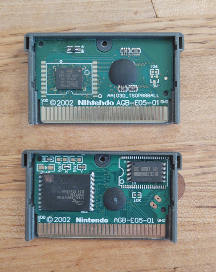
In order to flash data to the cart, you will need to know what chips are in the cart.
For this guide, I will assume the cart is using a S29GL128N chip. You can usually read the chip
by using a magnifying glass and looking at the text stamped on the chip.
If you are interested in the exact specifications of the chip, you will need to track down the data sheet for it. Here is the data sheet for the S29GL128N. It will tell you exactly how to communicate with the chip.
Thankfully, many different chips use the same protocols, so a save routine won't need to know the exact chip, but instead just a category of chips.
At a high level, flashing to the cart will consist of:
- Querying the cart for sector layout
- Erasing a sector
- Writing the data to the sector
This is accomplished by writing special values to the ROM, at special address locations.
Swapping of D0/D1
IMPORTANT NOTE: Many carts will swap the D0 and D1 lines!
This means when the specification says you need to write 0x55, then you actually need to write
0x56 because bits 0 and 1 are swapped (01010101 -> 01010110).
This also affects reading the sector layout, because the values you read will have bits 0 and 1 swapped as well.
This does not affect the data written to the ROM. If you want 0x4321 written to memory, then
just write 0x4321, because it will be swapped on write, and swapped again on read, cancelling it
out.
Understanding Commands
The table on page 57 shows the different commands available for the S29GL128N:
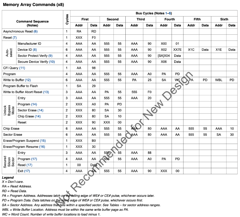
You can see that this information also exists in the FlashGBX source code, in the config:
"reset":[
  [ 0, 0xF0 ]
],
"read_identifier":[
  [ 0xAAA, 0xA9 ],
  [ 0x555, 0x56 ],
  [ 0xAAA, 0x90 ]
],
"read_cfi":[
  [ 0xAA, 0x98 ]
],
...
Notice that the "Auto-Select" row doesn't exactly match the "read_identifier" information.
Auto-Select starts with address 0xAAA, data 0xAA, but FlashGBX has address 0xAAA, data
0xA9 -- this is because D0/D1 are swapped (10101010 -> 10101001)! See the section
above.
So if we want to perform a reset on the chip, we just write 0xF0 to any address. Note that reset
doesn't erase the chip, it just resets any commands in progress.
// reset
*((u16 *)0x08000000) = 0xF0;
__asm("nop");
The forked goombacolor project from LesserKuma has example code, where you can see this happen:
#define _FLASH_WRITE(pa, pd) { *(((u16 *)AGB_ROM)+((pa)/2)) = pd; __asm("nop"); }

// reset
_FLASH_WRITE(0, 0xF0);
// auto-select
_FLASH_WRITE(0xAAA, 0xA9);
_FLASH_WRITE(0x555, 0x56);
_FLASH_WRITE(0xAAA, 0x90);
IMPORTANT NOTE: Since we need to control the reads/writes sent to the ROM, we cannot run the code from the ROM. You will need to load the code into EWRAM or IWRAM so that the bus between the GBA and the cart doesn't have extra reads to execute code.
Querying for Information
There is a standard protocol used by all flash chips called the Common Flash Memory Interface (CFI).
You can use CFI to query a lot of information about the chip you're interacting with. The chip specifications should have a section on CFI.
Two things in particular you probably want is whether D0/D1 are swapped, and the region layout.
Detecting if D0/D1 are Swapped
You can detect if D0/D1 are swapped by putting the chip in CFI mode, then reading the bytes at
0x20, 0x22, and 0x24. These values are hardcoded to 'Q', 'R', 'Y', but if D0/D1 are
swapped, you'll instead see 'R', 'Q', 'Z'.
Here is some example code:
// reset the chip
_FLASH_WRITE(0, 0xF0);
// enter CFI mode
_FLASH_WRITE(0xAA, 0x98);

// read the header
u16 Q = *(((u16 *)AGB_ROM)+(0x20/2));
u16 R = *(((u16 *)AGB_ROM)+(0x22/2));
u16 Y = *(((u16 *)AGB_ROM)+(0x24/2));
bool swapBits = false;

if (Q == 'Q' && R == 'R' && Y == 'Y') {
  // CFI mode is enabled, D0/D1 are not swapped
  swapBits = false;
}
else if (Q == 'R' && R == 'Q' && Y == 'Z') {
  // CFI mode is enabled, D0/D1 are swapped
  swapBits = true;
}
else {
  // chip didn't enter CFI mode, try something else
}
Once you know if D0/D1 are swapped, you can write a helper function for reading bytes from the ROM:
u8 readByte(int addr, bool swapBits) {
  u8 data = *(((u16 *)AGB_ROM)+(addr/2));
  if (swapBits) {
    data =
      (data & 0xfc) |
      ((data & 1) << 1) |
      ((data & 2) >> 1);
  }
  return data;
}
Understanding Region Layout
The region layout is useful for calculating where the sectors start, and how large they are. Assuming you want to overwrite sectors at the end of the ROM, you need to figure out what address(es) to write to.
There are 1-4 regions, and each region has a sector count and sector size.
After entering CFI mode, you can read the region layout from memory:
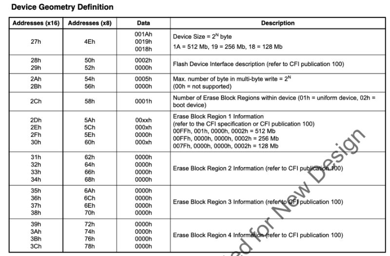
Here's some example code:
// assuming we are already in CFI mode
int regionCount = readByte(0x58, swapBits);
struct {
  int sectorCount;
  int sectorSize;
} regions[4] = {0};

for (int region = 0; region < regionCount; region++) {
  int sectorCountLow  = readByte(0x5A + region * 8, swapBits);
  int sectorCountHigh = readByte(0x5C + region * 8, swapBits);
  int sectorSizeLow   = readByte(0x5E + region * 8, swapBits);
  int sectorSizeHigh  = readByte(0x60 + region * 8, swapBits);

  // note we must add one!
  regions[region].sectorCount =
    ((sectorCountHigh << 8) | sectorCountLow) + 1;

  // note we must multiply by 256!
  regions[region].sectorSize =
    ((sectorSizeHigh << 8) | sectorSizeLow) << 8;
}
Erasing a Sector
Erasing a sector will set all the values in that sector to 0xFFFF.
This is fairly straight forward, you can use goombacolor as a reference:
// Erase flash sector
_FLASH_WRITE(sa, 0xF0);
_FLASH_WRITE(0xAAA, 0xA9);
_FLASH_WRITE(0x555, 0x56);
_FLASH_WRITE(0xAAA, 0x80);
_FLASH_WRITE(0xAAA, 0xA9);
_FLASH_WRITE(0x555, 0x56);
_FLASH_WRITE(sa, 0x30);
while (1) {
  __asm("nop");
  if (*(((u16 *)AGB_ROM)+(sa/2)) == 0xFFFF) {
    break;
  }
}
_FLASH_WRITE(sa, 0xF0);
You now should be able to understand this code.
This sequence of writes matches the documentation (with D0/D1 swapped).
The variable sa is the sector address. The code:
- Resets the chip
- Erases the sector
- Waits in a loop until it reads
0xFFFFfrom the sector, indicating the erase is finished - Resets the chip again
Saving Data
Once again, goombacolor is a great reference:
for (int i=0; i<AGB_SRAM_SIZE; i+=2) {
  _FLASH_WRITE(0xAAA, 0xA9);
  _FLASH_WRITE(0x555, 0x56);
  _FLASH_WRITE(0xAAA, 0xA0);
  _FLASH_WRITE(sa+i, (*(u8 *)(AGB_SRAM+i+1)) << 8 | (*(u8 *)(AGB_SRAM+i)));
  while (1) {
    __asm("nop");
    if (*(((u16 *)AGB_ROM)+((sa+i)/2)) == ((*(u8 *)(AGB_SRAM+i+1)) << 8 | (*(u8 *)(AGB_SRAM+i)))) {
      break;
    }
  }
}
_FLASH_WRITE(sa, 0xF0);
The code:
- Issues a "Program" command for each 16-bit value
- Writes the 16-bit value at the target address
- Waits in a loop until it reads the written value*
- Continues writing until all 16-bit values are written
- Resets the chip
Note that this code copies data from SRAM into the ROM. As a homebrew developer, you don't have to do it this way -- you can just write directly to the ROM. However, you should still have code that saves to SRAM so that emulators can save the data.
* You might think this loop could be incorrect if by chance, the read returns the value written before it was actually finished. See the section on DQ7 Data Polling on page 59 to understand why this won't happen. In summary, DQ7 will always be the opposite of whatever was written until the write goes through.
Final Thoughts
This guide is a starting point, but it cannot replace experimentation. Now that you understand the basic idea, here are some things you will want to consider:
- If a user shuts off power during a save, then the save will be incomplete. You can backup the save into another sector to ensure the data will always be recoverable.
- If you want your game to work on emulators, you will still need to save to SRAM. However, if you don't care about emulators, then you can have much larger save files (for example, reserving 8 MB for game code, 4 MB for save data, and 4 MB for backup).
- Different chips have different commands, so if you want to support multiple chips, you will need a method to detect which chip you're on, and use the appropriate commands. FlashGBX and goombacolor are great references for this, and they both use different methods.
Acknowledgements
- Velipso, author of the Bootleg Carts article.
The following are individuals who contributed info or corrections on the original CowBiteSpec document.
- Tom Happ
- Agent Q (Wrote the original spec, version 1.0)
- Uze (All of the sound register info comes directly from his Audio Advance site)
- Martin Korth (Author no$gba of who has given me permission to consolidate additional info from his emulator's informative help documents with this one, most particularly serial registers, some BIOS functions, and undocumented registers.)
- Forgotten (VBA Author. Many of the BIOS call descriptions come from his Visual Boy Advance FAQ.
- gbcft (LOTS of info on interrupts, windowing, memory mirrors, the "Unkown Registers" section; helped me debug a lot of errors in the emulator, and offered many corrections, info, and suggestions).
- Kay (Contributed memory port sizes and wait states, DMA cycle timings, info regarding the BIOS, and various advice, testing, and expertise regarding the GBA and older console systems)
- Damian Yerrick (Contributed the WSCOUNT register)
- Markus (Actually I asked him for help with LZSS. Also, his gfx2gba tool has proven extremely helpful in my non-CowBite projects.:)
- ePac (Gave me links to serial info and did a nice writeup about it in the gbadev group)
- Costis (A variety of new info/corrections)
- Grauw (Info on forced blanking, hblank lenghths, and on the BIOS wait function.)
- Max
- Otaku
- Ped (Pointed out errors in the memory ranges, DISPCNT bit 5, and a bad typo regarding rotates/scale backgrounds).
- Yarpen (Almost all the information on the timer registers and the keyboard control register. Thanks!)
- http://www.gbadev.org/
- The gbadev list on yahoo
- SimonB and all the others who run/moderate the above sites
- Dovoto and the PERN Project
- Jeff Frohwein and his Devrs.com site
- Nocturn and his tutorials
- Uze from BeLogic for all the great information on the GBA's sound!
- Andrew May for his site on GBA serial data
Thank you to Alec Bourque for allowing us to use all assets of The Audio Advance in this documentation.